STOP LIGHT SWITCH INSTALLATION
PROCEDURE
-
INSTALL STOP LIGHT SWITCH ASSEMBLY (for LHD)
-
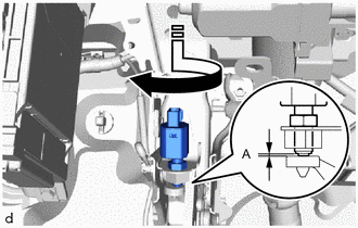

Install in this Direction Temporarily install the stop light switch assembly with the stop light switch lock nut as shown in the illustration.
-
Turn the stop light switch assembly so that the clearance between the end of the threads and cushion is within A.
Part Measurement A 0.87 to 2.4 mm (0.0343 to 0.0945 in.) Note
Do not depress the brake pedal.
-
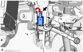
*a Union Nut Wrench *b Torque Wrench Fulcrum Length Using a union nut wrench and a torque wrench, tighten the lock nut.
- Torque:
- 16.7 N*m { 170 kgf*cm, 12 ft.*lbf }
Tech Tips
-
Calculate the torque wrench reading when changing the fulcrum length of the torque wrench.
-
When using union nut wrench (fulcrum length of 30 mm (1.18 in.)) + torque wrench (fulcrum length of 180 mm (7.09 in.)): 14.3 N*m (146 kgf*cm, 11 ft.*lbf)
-
Connect the connector.
-
-
INSTALL STOP LIGHT SWITCH ASSEMBLY (for RHD)
-
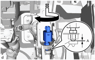
Temporarily install the stop light switch assembly with the stop light switch lock nut as shown in the illustration.
-
Turn the stop light switch assembly so that the clearance between the end of the threads and cushion is within A.
Part Measurement A 0.87 to 2.4 mm (0.0343 to 0.0945 in.) Note
Do not depress the brake pedal.
-
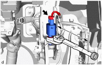
*a Union Nut Wrench *b Torque Wrench Fulcrum Length Using a union nut wrench and a torque wrench, tighten the lock nut.
- Torque:
- 16.7 N*m { 170 kgf*cm, 12 ft.*lbf }
Tech Tips
-
Calculate the torque wrench reading when changing the fulcrum length of the torque wrench.
-
When using union nut wrench (fulcrum length of 30 mm (1.18 in.)) + torque wrench (fulcrum length of 180 mm (7.09 in.)): 14.3 N*m (146 kgf*cm, 11 ft.*lbf)
-
Connect the connector.
-
-
INSTALL NO. 1 INSTRUMENT PANEL UNDER COVER SUB-ASSEMBLY