ADAPTIVE HIGH BEAM SYSTEM, Diagnostic DTC:B2440, B2441
| DTC Code | DTC Name |
|---|---|
| B2440 | Lost Communication with AHS EDU LH Module |
| B2441 | Lost Communication with AHS EDU RH Module |
DESCRIPTION
This DTC is output when there is a CAN communication malfunction between the headlight control computer assembly and headlight control computer assembly. The headlight control computer assembly LH outputs DTCs B2440 and B2441.
| DTC No. | Detection Item | DTC Detection Condition | Trouble Area |
|---|---|---|---|
| B2440 | Lost Communication with AHS EDU LH Module | Headlight control computer assembly LH communication malfunction |
|
| B2441 | Lost Communication with AHS EDU RH Module | Headlight control computer assembly RH communication malfunction |
|
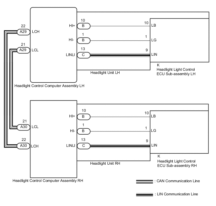
WIRING DIAGRAM
CAUTION / NOTICE / HINT
Note
If the headlight control computer assembly LH has been replaced, it is necessary to synchronize the vehicle information and initialize the headlight control computer assembly LH.
PROCEDURE
-
CLEAR DTC
-
Clear the DTCs.
Body Electrical > AFS > Clear DTCsResult Proceed to NEXT
NEXT 
-
-
CHECK FOR DTC
-
Check for DTCs.
Body Electrical > AFS > Trouble CodesOK DTC B2440 and B2441 are not output. Result Result Proceed to OK A NG (DTC B2440 is output) B NG (DTC B2441 is output) C
A 
USE SIMULATION METHOD TO CHECK Click here
C 
CHECK HARNESS AND CONNECTOR (HEADLIGHT CONTROL COMPUTER ASSEMBLY LH - HEADLIGHT CONTROL COMPUTER ASSEMBLY RH) Click here
B
-
-
INSPECT HEADLIGHT UNIT LH
-
Remove the headlight assembly LH.
-
Remove the headlight control computer assembly LH.
-
Remove the headlight light control ECU sub-assembly LH.
-
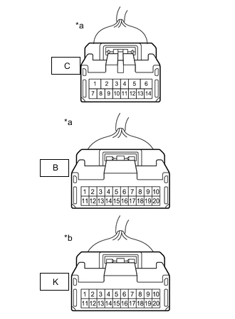
*a Component without harness connected
(Headlight Control Computer Assembly LH Side Connector)
*b Component without harness connected
(Headlight Light Control ECU Sub-assembly LH Side Connector)
Measure the resistance according to the value(s) in the table below.
Standard Voltage Tester Connection Condition Specified Condition B-10 - K-10 Always Below 1 Ω B-1 - K-1 Always Below 1 Ω C-13 - K-9 Always Below 1 Ω Result Proceed to OK NG
NG
REPLACE HEADLIGHT UNIT LH Click here
OK
-
-
REPLACE HEADLIGHT LIGHT CONTROL ECU SUB-ASSEMBLY LH
-
Replace the headlight light control ECU sub-assembly LH with a new or known good one.
-
Check for DTCs.
Body Electrical > AFS > Trouble CodesOK DTC B2440 is not output. Result Proceed to OK NG
OK
END (HEADLIGHT LIGHT CONTROL ECU SUB-ASSEMBLY LH WAS DEFECTIVE)
NG
REPLACE HEADLIGHT CONTROL COMPUTER ASSEMBLY LH Click here
-
-
CHECK HARNESS AND CONNECTOR (HEADLIGHT CONTROL COMPUTER ASSEMBLY LH - HEADLIGHT CONTROL COMPUTER ASSEMBLY RH)
-
Disconnect the A29 headlight control computer assembly LH connector.
-
Disconnect the A30 headlight control computer assembly RH connector.
-
Measure the voltage according to the value(s) in the table below.
Standard Voltage Tester Connection Condition Specified Condition A29-22 (LCH) - A30-22 (LCH) Always Below 1 Ω A29-21 (LCL) - A30-21 (LCL) Always Below 1 Ω A29-22 (LCH) or A30-22 (LCH) - Body ground Always 10 kΩ or higher A29-21 (LCL) or A30-21 (LCL) - Body ground Always Always Result Proceed to OK NG
NG
REPAIR OR REPLACE HARNESS OR CONNECTOR
OK
-
-
INSPECT HEADLIGHT UNIT RH
-
Remove the headlight assembly RH.
-
Remove the headlight control computer assembly RH.
-
Remove the headlight light control ECU sub-assembly RH.
-
*a Component without harness connected
(Headlight Control Computer Assembly RH Side Connector)
*b Component without harness connected
(Headlight Light Control ECU Sub-assembly RH Side Connector)
Measure the resistance according to the value(s) in the table below.
Standard Voltage Tester Connection Condition Specified Condition B-10 - K-10 Always Below 1 Ω B-1 - K-1 Always Below 1 Ω C-13 - K-9 Always Below 1 Ω Result Proceed to OK NG
NG
REPLACE HEADLIGHT UNIT RH Click here
OK
-
-
REPLACE HEADLIGHT LIGHT CONTROL ECU SUB-ASSEMBLY RH
-
Replace the headlight light control ECU sub-assembly RH with a new or known good one.
-
Check for DTCs.
Body Electrical > AFS > Trouble CodesOK DTC B2441 is not output. Result Proceed to OK NG
OK
END (HEADLIGHT LIGHT CONTROL ECU SUB-ASSEMBLY RH WAS DEFECTIVE)
NG
-
-
REPLACE HEADLIGHT CONTROL COMPUTER ASSEMBLY RH
-
Replace the headlight light control ECU sub-assembly RH with a new or known good one.
-
Check for DTCs.
Body Electrical > AFS > Trouble CodesOK DTC B2441 is not output. Result Proceed to OK NG
OK
END (HEADLIGHT CONTROL COMPUTER ASSEMBLY RH WAS DEFECTIVE)
NG
REPLACE HEADLIGHT CONTROL COMPUTER ASSEMBLY LH Click here
-