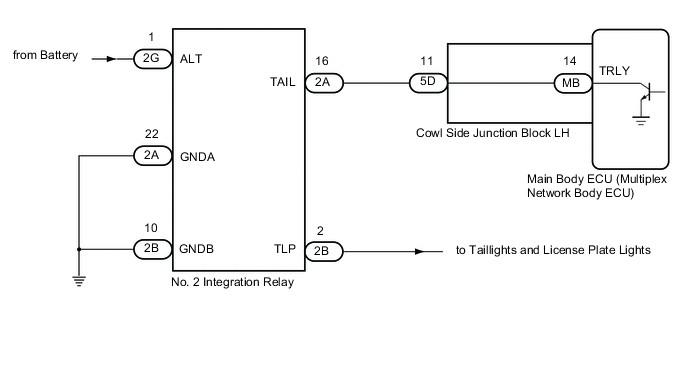
LIGHTING SYSTEM Taillight Relay Circuit
DESCRIPTION
The main body ECU (multiplex network body ECU) controls the operation of the TAIL relay.
WIRING DIAGRAM
CAUTION / NOTICE / HINT
Note
-
Inspect the fuses for circuits related to this system before performing the following procedure.
-
Before replacing the main body ECU (multiplex network body ECU), refer to Service Bulletin.
-
The vehicle battery supplies power to the main body ECU (multiplex network body ECU) via the door control battery. If a main body ECU (multiplex network body ECU) power source malfunction occurs, the door control battery may be malfunctioning.
PROCEDURE
-
PERFORM ACTIVE TEST USING GTS (TAILLIGHT RELAY)
-
Connect the GTS to the DLC3.
-
Turn the engine switch on (IG).
-
Turn the GTS on.
-
Enter the following menus: Body Electrical / Main Body / Active Test.
-
Perform the Active Test according to the display on the GTS.
Body Electrical > Main Body > Active TestTester Display Measurement Item Control Range Diagnostic Note Taillight Relay Taillight relay ON/OFF -
Body Electrical > Main Body > Active TestTester Display Taillight Relay OK Taillight relay operates. (Taillights illuminate.) Result Proceed to OK NG
OK 
PROCEED TO NEXT SUSPECTED AREA SHOWN IN PROBLEM SYMPTOMS TABLE Click here
NG 
-
-
CHECK HARNESS AND CONNECTOR (POWER SOURCE - NO. 2 INTEGRATION RELAY)
-
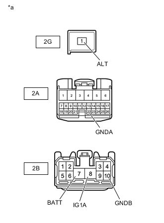
*a Front view of wire harness connector
(to No. 2 Integration Relay)
Disconnect the No. 2 integration relay connectors.
-
Measure the voltage according to the value(s) in the table below.
Standard Voltage Tester Connection Switch Condition Specified Condition 2G-1 (ALT) - Body ground Always 11 to 14 V 2B-7 (BATT) - Body ground 2B-8 (IG1A) - Body ground Engine switch on (IG) -
Measure the resistance according to the value(s) in the table below.
Standard Resistance Tester Connection Condition Specified Condition 2B-10 (GNDB) - Body ground Always Below 1 Ω 2A-22 (GNDA) - Body ground Result Proceed to OK NG
NG
REPAIR OR REPLACE HARNESS OR CONNECTOR
OK
-
-
CHECK HARNESS AND CONNECTOR (NO. 2 INTEGRATION RELAY - COWL SIDE JUNCTION BLOCK LH)
-
Disconnect the 2A No. 2 integration relay connector.
-
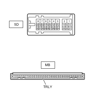
Disconnect the 5D cowl side junction block LH connector.
-
Measure the resistance according to the value(s) in the table below.
Standard Resistance Tester Connection Condition Specified Condition 2A-16 (TAIL) - 5D-11 Always Below 1 Ω 2A-16 (TAIL) - Body ground 10 kΩ or higher Result Proceed to OK NG
NG
REPAIR OR REPLACE HARNESS OR CONNECTOR
OK
-
-
INSPECT COWL SIDE JUNCTION BLOCK LH
-
Remove the cowl side junction block LH.
-
Remove the main body ECU from the cowl side junction block LH.
-
Measure the resistance according to the value(s) in the table below.
Standard Resistance Tester Connection Condition Specified Condition MB-14 (TRLY) - 5D-11 Always Below 1 Ω Result Proceed to OK NG
OK
PROCEED TO NEXT SUSPECTED AREA SHOWN IN PROBLEM SYMPTOMS TABLE Click here
NG
REPLACE COWL SIDE JUNCTION BLOCK LH Click here
-