LIGHTING SYSTEM Rear Fog Light Circuit
DESCRIPTION
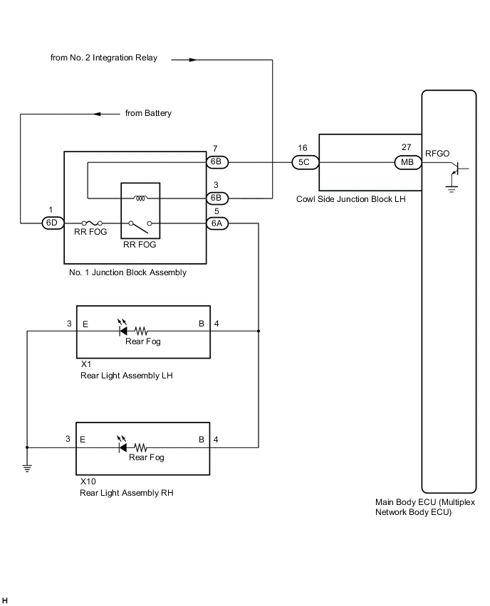
The main body ECU (multiplex network body ECU) controls the front fog lights.
WIRING DIAGRAM
CAUTION / NOTICE / HINT
Note
Inspect the fuses and bulbs for circuits related to this system before performing the following procedure.
PROCEDURE
-
CHECK OPERATION (TAILLIGHTS)
-
Check the operation of the taillights.
OK Taillights operate normally. Result Proceed to OK NG
NG 
GO TO PROBLEM SYMPTOMS TABLE Click here
OK 
-
-
PERFORM ACTIVE TEST USING GTS (REAR FOG LIGHT RELAY)
-
Connect the GTS to the DLC3.
-
Turn the engine switch to ON.
-
Turn the GTS on.
-
Enter the following menus: Body Electrical / Main Body / Active Test.
-
Check that the relay operates.
Body Electrical > Main Body > Active TestTester Display Measurement Item Control Range Diagnostic Note Rear Fog Light Relay Rear fog light relay ON/OFF Light control switch is in tail position
Body Electrical > Main Body > Active TestTester Display Rear Fog Light Relay OK Rear fog light relay operates. (Rear fog lights come on.) Result Proceed to OK NG
OK
PROCEED TO NEXT SUSPECTED AREA SHOWN IN PROBLEM SYMPTOMS TABLE Click here
NG
-
-
CHECK HARNESS AND CONNECTOR (RR FOG RELAY INPUT VOLTAGE)
-
Disconnect the No. 1 junction block assembly connector.
-
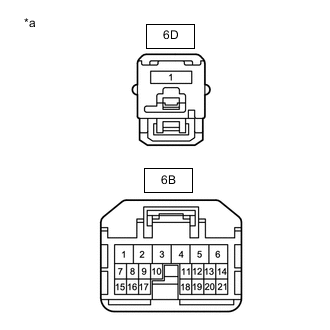
*a Front view of wire harness connector
(to No. 1 Junction Block Assembly)
Measure the voltage according to the value(s) in the table below.
Standard Voltage Tester Connection Switch Condition Specified Condition 6B-3 - Body ground Taillights on 11 to 14 V 6D-1 - Body ground Always 11 to 14 V Result Proceed to OK NG
NG
REPAIR OR REPLACE HARNESS OR CONNECTOR
OK
-
-
INSPECT NO. 1 JUNCTION BLOCK ASSEMBLY
-
Remove the No. 1 junction block assembly.
-
Connect a positive (+) lead from the battery to terminal 6B-3.
-
Connect a negative (-) lead from the battery to terminal 6B-7.
-
Measure the voltage according to the value(s) in the table below.
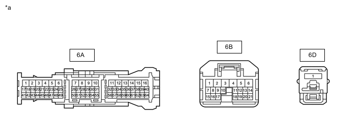
*a Component without harness connected
(No. 1 Junction Block Assembly)
- - Standard Voltage Tester Connection Condition Specified Condition 6A-5 - Battery negative (-) terminal Always 11 to 14 V Result Proceed to OK NG
NG
REPLACE JUNCTION BLOCK COVER
OK
-
-
CHECK HARNESS AND CONNECTOR (NO. 1 JUNCTION ASSEMBLY - REAR LIGHT AND BODY)
-
Disconnect the X1 rear light assembly LH connector.
-
Disconnect the X10 rear light assembly RH connector.
-
Measure the resistance according to the value(s) in the table below.
Standard Resistance Tester Connection Condition Specified Condition 6A-5 - X1-4(B) Always Below 1 Ω 6A-5 - X10-4(B) Always Below 1 Ω 6A-5 - Body ground Always 10 kΩ or higher Result Proceed to OK NG
NG
REPAIR OR REPLACE HARNESS OR CONNECTOR
OK
-
-
CHECK HARNESS AND CONNECTOR (NO. 1 JUNCTION BLOCK ASSEMBLY - COWL SIDE JUNCTION BLOCK LH)
-
Disconnect the 5C cowl side junction block LH connector.
-
Disconnect the 6B No. 1 junction block assembly connector.
-
Measure the resistance according to the value(s) in the table below.
Standard Resistance Tester Connection Condition Specified Condition 6B-7 - 5C-16 Always Below 1 Ω 6B-7 - Body ground Always 10 kΩ or higher Result Proceed to OK NG
NG
REPAIR OR REPLACE HARNESS OR CONNECTOR
OK
-
-
INSPECT COWL SIDE JUNCTION BLOCK LH
-
Remove the cowl side junction block LH.
-
for LHD: Click here
-
for RHD: Click here
-
-
Remove the main body ECU (multiplex network body ECU) from the cowl side junction block LH.
-
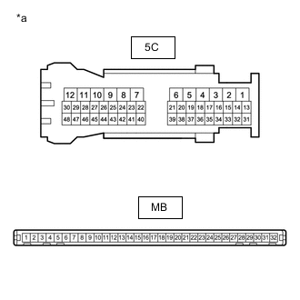
*a Component without harness connected
(Cowl Side Junction Block LH)
Measure the resistance according to the value(s) in the table below.
Standard Resistance Tester Connection Condition Specified Condition 5C-16 - MB-27 (RFGO) Always Below 1 Ω Result Proceed to OK NG
OK
REPLACE MAIN BODY ECU (MULTIPLEX NETWORK BODY ECU)
NG
REPLACE COWL SIDE JUNCTION BLOCK LH Click here
-