LIGHTING SYSTEM, Diagnostic DTC:U0242
| DTC Code | DTC Name |
|---|---|
| U0242 | Lost Communication With Headlamp Control Module "B" |
DESCRIPTION
This DTC is output when a headlight control computer assembly RH internal malfunctioning or the communication malfunction between headlight control computer assembly LH and headlight control computer assembly RH is 10 seconds or more.
The headlight control computer assembly LH outputs DTC U0242.
| DTC No. | Detection Item | DTC Detection Condition | Trouble Area |
|---|---|---|---|
| U0242 | Lost Communication With Headlamp Control Module "B" |
|
|
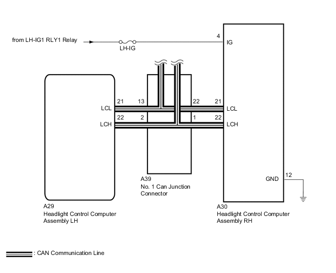
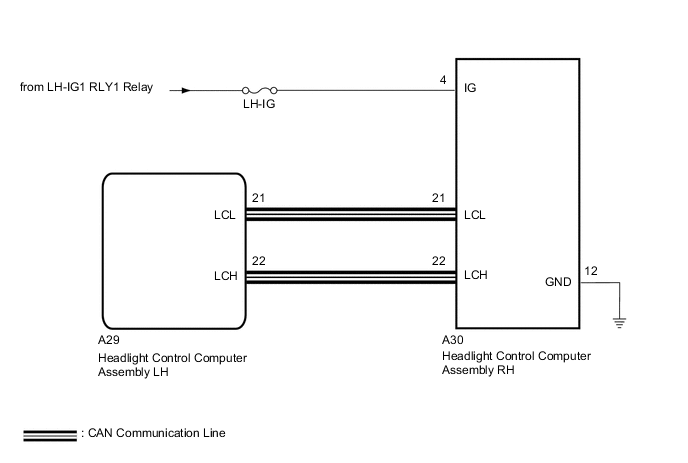
WIRING DIAGRAM
-
w/ Adaptive High Beam System
-
w/o Adaptive High Beam System
CAUTION / NOTICE / HINT
Note
After the headlight control computer assembly LH (main) is replaced, vehicle information registration and initialization are necessary.
PROCEDURE
-
CLEAR DTC
-
Clear the DTCs.
Body Electrical > AFS > Clear DTCsResult Proceed to NEXT
NEXT 
-
-
CHECK FOR DTC
-
Turn the engine switch on (IG).
-
Turn on the headlights using the headlight dimmer switch.
-
Check for DTCs.
OK DTC U0242 are not output. Result Result Proceed to OK A NG (w/ Adaptive High Beam System) B NG (w/o Adaptive High Beam System)(for LHD) C NG (w/o Adaptive High Beam System)(for RHD) D
A 
USE SIMULATION METHOD TO CHECK Click here
C
GO TO CAN COMMUNICATION SYSTEM Click here
D
GO TO CAN COMMUNICATION SYSTEM Click here
B
-
-
CHECK HARNESS AND CONNECTOR (HEADLIGHT CONTROL COMPUTER ASSEMBLY LH - NO. 1 CAN JUNCTION CONNECTOR)
-
Cable disconnected from negative (-) battery terminal.
-
Disconnect the A39 No. 1 CAN junction connector.
-
Measure the resistance according to the value(s) in the table below.
Standard Resistance Tester Connection Condition Specified Condition A39-13 - A39-3 Cable disconnectedfrom negative (-) batteryterminal Below 1 Ω A39-12 - A39-1 Cable disconnectedfrom negative (-) batteryterminal 10 kΩ or higher Result Proceed to OK NG
NG 
CHECK HARNESS AND CONNECTOR (HEADLIGHT CONTROL COMPUTER ASSEMBLY RH - NO. 1 CAN JUNCTION CONNECTOR) Click here
OK
-
-
CHECK HARNESS AND CONNECTOR (HEADLIGHT CONTROL COMPUTER ASSEMBLY RH - POWER SOURCE AND BODY GROUND)
-
Cable disconnected from negative (-) battery terminal.
-
Disconnect the A30 headlight control computer assembly RH connector.
-
Measure the voltage according to the value(s) in the table below.
Standard Voltage Tester Connection Switch Condition Specified Condition A30-4 (IG) - Body ground Engine switch on (IG) 11 to 14 V -
Measure the resistance according to the value(s) in the table below.
Standard Resistance Tester Connection Switch Condition Specified Condition A30-12 (GND) - Body ground Always Below 1 Ω Result Proceed to OK NG
NG
REPAIR OR REPLACE HARNESS OR CONNECTOR
OK
-
-
REPLACE HEADLIGHT CONTROL COMPUTER ASSEMBLY RH
-
Replace the headlight control computer assembly RH with a new or normally functioning one.
-
Turn the engine switch on (IG).
-
Turn on the headlights using the headlight dimmer switch.
-
Clear the DTCs
-
Check for DTCs
Result Proceed to OK NG
OK
HEADLIGHT CONTROL COMPUTER ASSEMBLY RH (HEADLIGHT ECU SUB-ASSEMBLY RH WAS DEFECTIVE)
NG
-
-
CHECK FOR DTC
-
Reconnect the A39 No. 1 CAN junction connector.
-
Turn the engine switch on (IG).
-
Turn on the headlights using the headlight dimmer switch.
-
Clear the DTCs
-
Check for DTCs.
Body Electrical > AFS > Trouble CodesOK DTC U0242 are not output. Result Proceed to OK NG
OK
USE SIMULATION METHOD TO CHECK Click here
NG
REPLACE HEADLIGHT CONTROL COMPUTER ASSEMBLY LH Click here
-
-
CHECK HARNESS AND CONNECTOR (HEADLIGHT CONTROL COMPUTER ASSEMBLY RH - NO. 1 CAN JUNCTION CONNECTOR)
-
Reconnect the A39 No. 1 CAN junction connector.
-
Disconnect the A29 headlight control computer assembly LH connector.
-
Disconnect the A30 headlight control computer assembly RH connector.
-
Measure the resistance according to the value(s) in the table below.
Standard Resistance Tester Connection Switch Condition Specified Condition A30-22 (LCH) - A30-21 (LCH) Cable disconnected from negative (-) battery terminal 54 Ω to 69 Ω A30-22 (LCH) - A30-21 (LCH) Cable disconnected from negative (-) battery terminal 54 Ω to 69 Ω Result Proceed to OK NG
OK
CHECK HEADLIGHT CONTROL COMPUTER ASSEMBLY LH
NG
REPAIR OR REPLACE HARNESS OR CONNECTOR
-