WIPER SWITCH REMOVAL
CAUTION / NOTICE / HINT
The necessary procedures (adjustment, calibration, initialization, or registration) that must be performed after parts are removed, installed, or replaced during the wiper switch assembly removal/installation are shown below.
| Replacement Part or Procedure | Necessary Procedure | Effect/Inoperative when not Performed | Link |
|---|---|---|---|
| Disconnect cable from negative battery terminal | Correct the steering angle neutral point | Parking assist monitor system | |
| Lane departure alert system (w/ Steering Control) | |||
| Pre-crash safety system | |||
| Adaptive high beam system | |||
| Reset power trunk lid | Power trunk lid system |
PROCEDURE
-
CUSTOMIZE CHANGE POWER TILT AND POWER TELESCOPIC STEERING COLUMN SYSTEM
-
PRECAUTION
Note
After turning the engine switch off, waiting time may be required before disconnecting the cable from the battery terminal. Therefore, make sure to read the disconnecting the cable from the battery terminal notice before proceeding with work.
-
DISCONNECT CABLE FROM NEGATIVE BATTERY TERMINAL
-
REMOVE STEERING COLUMN COVER
-
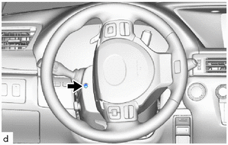
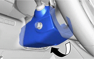
Turn the steering wheel assembly to the left and remove the screw.
-
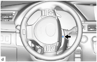
Turn the steering wheel assembly to the right and remove the screw.
-
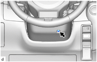
Remove the screw.
-
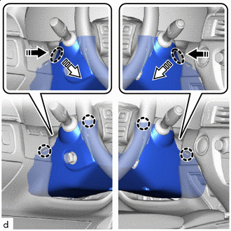

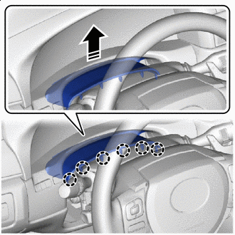
Place Hands Here 
Remove in this Direction (1) 
Remove in this Direction (2) Push the left and right of the steering column lower cover to disengage the claws as shown in the illustration.
-
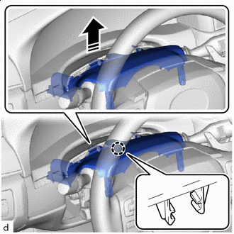
Remove the steering column lower cover as shown in the illustration.
-
Remove in this Direction Disengage the claws to separate the meter hood spacer as shown in the illustration.
-
Remove in this Direction Disengage the claw to remove the steering column upper cover as shown in the illustration.
-
-
REMOVE WINDSHIELD WIPER SWITCH ASSEMBLY
-
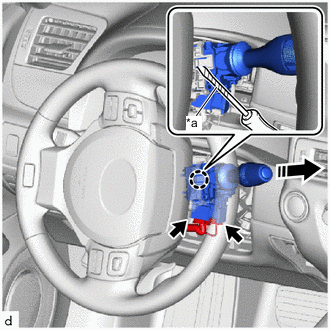
*a Protective Tape Remove in this Direction Disconnect 2 connectors.
-
Using a screwdriver with its tip wrapped in protective tape, disengage the claw to remove the windshield wiper switch assembly as shown in the illustration.
Note
If the claw is pulled with excessive force, it may break.
-