POWER MIRROR CONTROL SYSTEM TERMINALS OF ECU
-
CHECK FRONT MULTIPLEX NETWORK DOOR ECU (DRIVER DOOR)
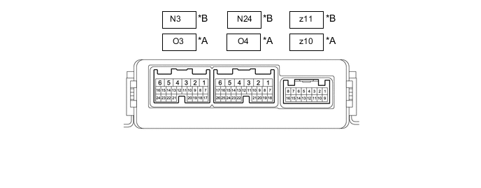
*A for LHD *B for RHD
-
Disconnect the O4*1 or N24*2 outer mirror control ECU assembly (driver door) connector.
-
*1: for LHD
-
*2: for RHD
-
-
Measure the voltage and resistance according to the value(s) in the table below.
Tech Tips
Measure the values on the wire harness side with the connector disconnected.
for LHD Terminal No. (Symbol) Wiring Color Terminal Description Condition Specified Condition O4-6 (BDR) - Body ground V - Body ground +B power supply Always 11 to 14 V O4-4 (CPUB) - Body ground P - Body ground +B power supply Always 11 to 14 V O4-3 (SIG) - Body ground B - Body ground Ignition power supply Engine switch off → on (IG) Below 1 V → 11 to 14 V O4-1 (GND) - Body ground W-B - Body ground Ground Always Below 1 Ω for RHD Terminal No. (Symbol) Wiring Color Terminal Description Condition Specified Condition N24-6 (BDR) - Body ground V - Body ground +B power supply Always 11 to 14 V N24-4 (CPUB) - Body ground P - Body ground +B power supply Always 11 to 14 V N24-3 (SIG) - Body ground B - Body ground Ignition power supply Engine switch off → on (IG) Below 1 V → 11 to 14 V N24-1 (GND) - Body ground W-B - Body ground Ground Always Below 1 Ω -
Reconnect the O4*1 or N24*2 outer mirror control ECU assembly (driver door) connector.
-
*1: for LHD
-
*2: for RHD
-
-
Measure the voltage according to the value(s) in the table below.
for LHD Terminal No. (Symbol) Wiring Color Terminal Description Condition Specified Condition z10-3 (MR) - Body ground G - Body ground Power retract mirror motor drive voltage*
-
Engine switch on (ACC)
-
Outer rear view mirror assembly being retracted
11 to 14 V
-
Engine switch on (ACC)
-
Outer rear view mirror assembly stopped
Below 1 V z10-11 (MF) - Body ground L - Body ground Power retract mirror motor drive voltage*
-
Engine switch on (ACC)
-
Outer rear view mirror assembly returning
11 to 14 V
-
Engine switch on (ACC)
-
Outer rear view mirror assembly stopped
Below 1 V z10-1 (MV) - z10-10 (M+) W - B Vertical mirror motor drive voltage Driver door mirror surface moving upward → stopped 11 to 14 V → Below 1 V z10-10 (M+) - z10-1 (MV) B - W Vertical mirror motor drive voltage Driver door mirror surface moving downward → stopped 11 to 14 V → Below 1 V z10-10 (M+) - z10-9 (MH) B - R Horizontal mirror motor drive voltage Driver door mirror surface moving right → stopped 11 to 14 V → Below 1 V z10-9 (MH) - z10-10 (M+) R - B Horizontal mirror motor drive voltage Driver door mirror surface moving left → stopped 11 to 14 V → Below 1 V z10-4 (+) - z10-12 (-) BR-W - B-R Mirror heater relay drive voltage Mirror heater switch (rear window defogger switch) on 11 to 14 V z10-5 (VC) - O4-1 (GND) SB - W-B Mirror position sensor power supply Engine switch on (IG) 4.75 to 5.25 V z10-6 (VSRL) - O4-1 (GND) V - W-B Mirror position sensor signal Engine switch on (IG) 0 to 5 V z10-13 (HSRL) - O4-1 (GND) LG - W-B Mirror position sensor signal Engine switch on (IG) 0 to 5 V z10-7 (EC+) - z10-15 (EC-) BR - B-L Automatic glare-resistant EC mirror drive signal Automatic glare-resistant EC mirror on 1.05 to 1.35 V Automatic glare-resistant EC mirror off Below 1 V O4-24 (M3) - O4-1 (GND) V - W-B M3 switch signal for seat memory switch M3 switch on Below 1 V M3 switch off 11 to 14 V O4-23 (M2) - O4-1 (GND) SB - W-B M2 switch signal for seat memory switch M2 switch on Below 1 V M2 switch off 11 to 14 V O4-22 (M1) - O4-1 (GND) B - W-B M1 switch signal for seat memory switch M1 switch on Below 1 V M1 switch off 11 to 14 V O4-25 (MM) - O4-1 (GND) LG - W-B SET switch signal for seat memory switch SET switch on Below 1 V SET switch off 11 to 14 V for RHD Terminal No. (Symbol) Wiring Color Terminal Description Condition Specified Condition z11-3 (MR) - Body ground G - Body ground Power retract mirror motor drive voltage*
-
Engine switch on (ACC)
-
Outer rear view mirror assembly being retracted
11 to 14 V
-
Engine switch on (ACC)
-
Outer rear view mirror assembly stopped
Below 1 V z11-11 (MF) - Body ground L - Body ground Power retract mirror motor drive voltage*
-
Engine switch on (ACC)
-
Outer rear view mirror assembly returning
11 to 14 V
-
Engine switch on (ACC)
-
Outer rear view mirror assembly stopped
Below 1 V z11-1 (MV) - z11-10 (M+) W - B Vertical mirror motor drive voltage Driver door mirror surface moving upward → stopped 11 to 14 V → Below 1 V z11-10 (M+) - z11-1 (MV) B - W Vertical mirror motor drive voltage Driver door mirror surface moving downward → stopped 11 to 14 V → Below 1 V z11-10 (M+) - z11-9 (MH) B - R Horizontal mirror motor drive voltage Driver door mirror surface moving right → stopped 11 to 14 V → Below 1 V z11-9 (MH) - z11-10 (M+) R - B Horizontal mirror motor drive voltage Driver door mirror surface moving left → stopped 11 to 14 V → Below 1 V z11-4 (+) - z11-12 (-) BR-W - B-R Mirror heater relay drive voltage Mirror heater switch (rear window defogger switch) on 11 to 14 V z11-5 (VC) - N24-1 (GND) SB - W-B Mirror position sensor power supply Engine switch on (IG) 4.75 to 5.25 V z11-6 (VSSR) - N24-1(GND) V - W-B Mirror position sensor signal Engine switch on (IG) 0 to 5 V z11-13 (HSSR) -N24-1 (GND) LG - W-B Mirror position sensor signal Engine switch on (IG) 0 to 5 V z11-7 (EC+) - z11-15 (EC-) BR - B-L Automatic glare-resistant EC mirror drive signal Automatic glare-resistant EC mirror on 1.05 to 1.35 V Automatic glare-resistant EC mirror off Below 1 V N24-24 (M3) - N24-1 (GND) V - W-B M3 switch signal for seat memory switch M3 switch on Below 1 V M3 switch off 11 to 14 V N24-23 (M2) - N24-1 (GND) SB - W-B M2 switch signal for seat memory switch M2 switch on Below 1 V M2 switch off 11 to 14 V N24-22 (M1) - N24-1 (GND) B - W-B M1 switch signal for seat memory switch M1 switch on Below 1 V M1 switch off 11 to 14 V N24-25 (MM) - N24-1 (GND) LG - W-B SET switch signal for seat memory switch SET switch on Below 1 V SET switch off 11 to 14 V
-
*: w/ Power Retract Mirror
-
-
-
CHECK FRONT MULTIPLEX NETWORK DOOR ECU (FRONT PASSENGER DOOR)
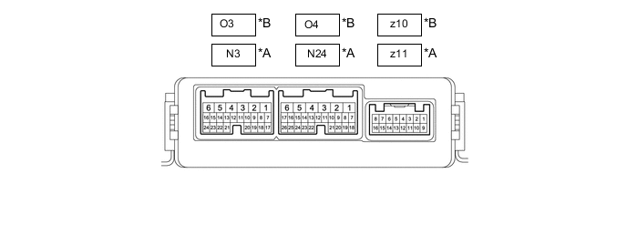
*A for LHD *B for RHD
-
Disconnect the N24*1 or O4*2 outer mirror control ECU assembly (front passenger door) connector.
-
*1: for LHD
-
*2: for RHD
-
-
Measure the voltage and resistance according to the value(s) in the table below.
Tech Tips
Measure the values on the wire harness side with the connector disconnected.
for LHD Terminal No. (Symbol) Wiring Color Terminal Description Condition Specified Condition N24-6 (BDR) - Body ground V - Body ground +B power supply Always 11 to 14 V N24-4 (CPUB) - Body ground P - Body ground +B power supply Always 11 to 14 V N24-3 (SIG) - Body ground B - Body ground Ignition power supply Engine switch off → on (IG) Below 1 V → 11 to 14 V N24-1 (GND) - Body ground W-B - Body ground Ground Always Below 1 Ω for RHD Terminal No. (Symbol) Wiring Color Terminal Description Condition Specified Condition O4-6 (BDR) - Body ground V - Body ground +B power supply Always 11 to 14 V O4-4 (CPUB) - Body ground P - Body ground +B power supply Always 11 to 14 V O4-3 (SIG) - Body ground B - Body ground Ignition power supply Engine switch off → on (IG) Below 1 V → 11 to 14 V O4-1 (GND) - Body ground W-B - Body ground Ground Always Below 1 Ω -
Reconnect the N24*1 or O4*2 outer mirror control ECU assembly (front passenger door) connector.
-
*1: for LHD
-
*2: for RHD
-
-
Measure the voltage according to the value(s) in the table below.
for LHD Terminal No. (Symbol) Wiring Color Terminal Description Condition Specified Condition z11-3 (MR) - Body ground G - Body ground Power retract mirror motor drive voltage*
-
Engine switch on (ACC)
-
Outer rear view mirror assembly being retracted
11 to 14 V
-
Engine switch on (ACC)
-
Outer rear view mirror assembly stopped
Below 1 V z11-11 (MF) - Body ground L - Body ground Power retract mirror motor drive voltage*
-
Engine switch on (ACC)
-
Outer rear view mirror assembly returning
11 to 14 V
-
Engine switch on (ACC)
-
Outer rear view mirror assembly stopped
Below 1 V z11-1 (MV) - z11-10 (M+) W - B Vertical mirror motor drive voltage Front passenger door mirror surface moving upward → stopped 11 to 14 V → Below 1 V z11-10 (M+) - z11-1 (MV) B - W Vertical mirror motor drive voltage Front passenger door mirror surface moving downward → stopped 11 to 14 V → Below 1 V z11-10 (M+) - z11-9 (MH) B - R Horizontal mirror motor drive voltage Front passenger door mirror surface moving right → stopped 11 to 14 V → Below 1 V z11-9 (MH) - z11-10 (M+) R - B Horizontal mirror motor drive voltage Front passenger door mirror surface moving left → stopped 11 to 14 V → Below 1 V z11-4 (+) - z11-12 (-) BR-W - B-R Mirror heater relay drive voltage Mirror heater switch (rear window defogger switch) on 11 to 14 V z11-5 (VC) - N24-1 (GND) SB - W-B Mirror position sensor power supply Engine switch on (IG) 4.75 to 5.25 V z11-6 (VSSR) - N24-1 (GND) V - W-B Mirror position sensor signal Engine switch on (IG) 0 to 5 V z11-13 (HSSR) - N24-1 (GND) LG - W-B Mirror position sensor signal Engine switch on (IG) 0 to 5 V z11-7 (EC+) - z11-15 (EC-) BR - B-L Automatic glare-resistant EC mirror drive signal Automatic glare-resistant EC mirror on 1.05 to 1.35 V Automatic glare-resistant EC mirror off Below 1 V for RHD Terminal No. (Symbol) Wiring Color Terminal Description Condition Specified Condition z10-3 (MR) - Body ground G - Body ground Power retract mirror motor drive voltage*
-
Engine switch on (ACC)
-
Outer rear view mirror assembly being retracted
11 to 14 V
-
Engine switch on (ACC)
-
Outer rear view mirror assembly stopped
Below 1 V z10-11 (MF) - Body ground L - Body ground Power retract mirror motor drive voltage*
-
Engine switch on (ACC)
-
Outer rear view mirror assembly returning
11 to 14 V
-
Engine switch on (ACC)
-
Outer rear view mirror assembly stopped
Below 1 V z10-1 (MV) - z10-10 (M+) W - B Vertical mirror motor drive voltage Front passenger door mirror surface moving upward → stopped 11 to 14 V → Below 1 V z10-10 (M+) - z10-1 (MV) B - W Vertical mirror motor drive voltage Front passenger door mirror surface moving downward → stopped 11 to 14 V → Below 1 V z10-10 (M+) - z10-9 (MH) B - R Horizontal mirror motor drive voltage Front passenger door mirror surface moving right → stopped 11 to 14 V → Below 1 V z10-9 (MH) - z10-10 (M+) R - B Horizontal mirror motor drive voltage Front passenger door mirror surface moving left → stopped 11 to 14 V → Below 1 V z10-4 (+) - z10-12 (-) BR-W - B-R Mirror heater relay drive voltage Mirror heater switch (rear window defogger switch) on 11 to 14 V z10-5 (VC) - O4-1 (GND) SB - W-B Mirror position sensor power supply Engine switch on (IG) 4.75 to 5.25 V z10-6 (VSRL) -O4-1 (GND) V - W-B Mirror position sensor signal Engine switch on (IG) 0 to 5 V z10-13 (HSRL) -O4-1 (GND) LG - W-B Mirror position sensor signal Engine switch on (IG) 0 to 5 V z10-7 (EC+) - z10-15 (EC-) BR - B-L Automatic glare-resistant EC mirror drive signal Automatic glare-resistant EC mirror on 1.05 to 1.35 V Automatic glare-resistant EC mirror off Below 1 V
-
*: w/ Power Retract Mirror
-
-