FRONT DOOR ADJUSTMENT

CAUTION / NOTICE / HINT
Tech Tips
-
Use the same procedures for both the LH and RH sides.
-
The procedure described below is for the LH side.
-
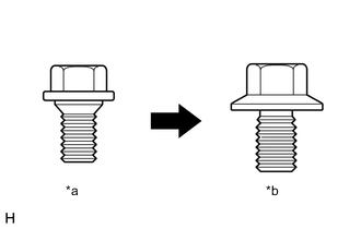
*a Centering Bolt *b Standard Bolt Centering bolts are used to mount the door hinge to the vehicle body and door. The door cannot be adjusted with the centering bolts on. Substitute the centering bolts for standard bolts when making adjustments.
-
A bolt without a torque specification is shown in the standard bolt chart Click here.
PROCEDURE
-
INSPECT FRONT DOOR PANEL SUB-ASSEMBLY
-
Check that the clearance measurements of areas A to R are within the standard ranges.
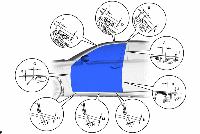
Standard Area Specified Condition Area Specified Condition A 3 to 7 mm (0.118 to 0.276 in.) B 1.2 to 5.2 mm (0.047 to 0.205 in.) C 3 to 7 mm (0.118 to 0.276 in.) D 1.1 to 5.1 mm (0.043 to 0.201 in.) E 3.5 to 6.5 mm (0.138 to 0.256 in.) F 0.5 to 3.5 mm (0.020 to 0.138 in.) G 2.5 to 6.5 mm (0.098 to 0.256 in.) H -2 to 2 mm (-0.079 to 0.079 in.) I 4.1 mm (0.161 in.) J 0 mm (0 in.) K 3.3 to 6.5 mm (0.130 to 0.256 in.) L -1.5 to 2.5 mm (-0.059 to 0.098 in.) M 3.3 to 6.5 mm (0.130 to 0.256 in.) N -1.6 to 2.4 mm (-0.063 to 0.094 in.) O 3.3 to 6.5 mm (0.130 to 0.256 in.) P 1.8 to 2.2 mm (0.071 to 0.087 in.) Q 3.8 mm (0.150 in.) R 0 mm (0 in.)
-
-
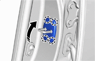
REMOVE FRONT DOOR LOCK STRIKER COVER
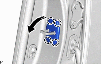

Remove in this Direction
-
Disengage the claws to remove the front door lock striker cover as shown in the illustration.
-
-
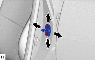
ADJUST FRONT DOOR PANEL SUB-ASSEMBLY
-
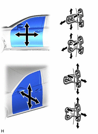
Using SST, loosen the 4 hinge bolts on the body and adjust the door position.
- SST
- 09812-00010
-
Tighten the 4 hinge bolts on the body after the adjustment.
- Torque:
- 26 N*m { 265 kgf*cm, 19 ft.*lbf }
-
Loosen the 4 hinge bolts on the door and adjust the door position.
-
Tighten the 4 hinge bolts on the door after the adjustment.
- Torque:
- 21 N*m { 214 kgf*cm, 15 ft.*lbf }
-
Using a T40 "TORX" socket wrench, slightly loosen the 2 striker mounting screws.
-
Using a brass bar and a hammer, hit the striker to adjust its position.
-
Using a T40 "TORX" socket wrench, tighten the 2 striker mounting screws after adjustment.
- Torque:
- 23 N*m { 235 kgf*cm, 17 ft.*lbf }
-
-
INSTALL FRONT DOOR LOCK STRIKER COVER
-
Install in this Direction Engage the claws to install the front door lock striker cover as shown in the illustration.
-