LUGGAGE COMPARTMENT DOOR CLOSER SYSTEM Luggage Compartment Door Closer does not Operate
DESCRIPTION
The luggage compartment door closer is controlled by the luggage closer motor assembly*1 or multiplex network door ECU*2. The luggage closer motor assembly*1 or multiplex network door ECU*2 is activated according to the switch signals in the luggage door closer assembly.
-
*1: w/ Power Trunk Lid System
-
*2: w/o Power Trunk Lid System
CAUTION / NOTICE / HINT
Note
-
First perform the communication function inspections in How to Proceed with Troubleshooting to confirm that there are no CAN communication malfunctions before troubleshooting this problem.
-
Inspect the fuses for circuits related to this system before performing the following inspection procedure.
-
If the main body ECU (multiplex network body ECU) is replaced, refer to the Service Bulletin.
-
This check is possible only when the "PBD Power Operation"*1 or "Closer Power Operation"*2 customization setting using the GTS is set to ON (initial setting is ON).
-
*1: w/ Power Trunk Lid System
-
*2: w/o Power Trunk Lid System
PROCEDURE
-
SYSTEM CHECK
-
Check the vehicle specifications.
Result Result Proceed to w/ Power Trunk Lid System. A w/o Power Trunk Lid System. B
B 
OPERATION INSPECTION Click here
A 
-
-
OPERATION INSPECTION
-
Confirm the problem symptoms.
Result Result Proceed to The luggage compartment door does not operate properly. A The luggage compartment door does not operate properly when the luggage compartment door lock cylinder is operated. B The luggage compartment door does not operate properly when the luggage electrical key switch is operated. C
B
READ VALUE USING GTS Click here
C 
GO TO ENTRY AND START SYSTEM (for Entry Function) Click here
A
-
-
READ VALUE USING GTS
-
Connect the GTS to the DLC3.
-
Turn the engine switch on (IG).
-
Turn the GTS on.
-
Enter the following menus: Body Electrical > Back Door > Data List.
-
Read the Data List according to the display on the GTS.
Body Electrical > Back Door > Data ListTester Display Measurement Item Range Normal Condition Diagnostic Note Half Latch SW Luggage door closer assembly (half switch signal) OFF or ON OFF: Half switch of luggage door closer assembly off
ON: Half switch of luggage door closer assembly on
See "Luggage Compartment Door Closer Operation Timing Chart"* Pawl Position Switch Luggage door closer assembly (pawl switch signal) OFF or ON OFF: Pawl switch of luggage door closer assembly off
ON: Pawl switch of luggage door closer assembly on
See "Luggage Compartment Door Closer Operation Timing Chart"*
Body Electrical > Back Door > Data ListTester Display Half Latch SW Pawl Position Switch
-
*: See "Luggage Compartment Door Closer Operation Timing Chart"
OK On the GTS screen, each item changes between ON and OFF as shown in above chart. Result Proceed to OK NG -
OK
REPLACE LUGGAGE CLOSER MOTOR ASSEMBLY Click here
NG
-
-
CHECK HARNESS AND CONNECTOR (LUGGAGE CLOSER MOTOR ASSEMBLY - BATTERY AND BODY GROUND)
-
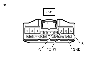
*a Front view of wire harness connector
(to Luggage Closer Motor Assembly)
Disconnect the luggage closer motor assembly connector.
-
Measure the resistance according to the value(s) in the table below.
Standard Resistance Tester Connection Condition Specified Condition U28-11 (GND) - Body ground Always Below 1 Ω -
Measure the voltage according to the value(s) in the table below.
Standard Voltage Tester Connection Switch Condition Specified Condition U28-8 (IG) - Body ground Engine switch on (IG) 11 to 14 V U28-10 (ECUB) - Body ground Always 11 to 14 V U28-12 (B) - Body ground Always 11 to 14 V Result Proceed to OK NG
NG
REPAIR OR REPLACE HARNESS OR CONNECTOR
OK
-
-
INSPECT LUGGAGE DOOR CLOSER ASSEMBLY
-
Remove the luggage door closer assembly.
-
Inspect the luggage door closer assembly
Result Proceed to OK NG
NG
REPLACE LUGGAGE DOOR CLOSER ASSEMBLY Click here
OK
-
-
CHECK HARNESS AND CONNECTOR (LUGGAGE CLOSER MOTOR ASSEMBLY - LUGGAGE DOOR CLOSER ASSEMBLY)
-
Disconnect the U28 luggage closer motor assembly connector.
-
Disconnect the X9 luggage door closer assembly connector.
-
Measure the resistance according to the value(s) in the table below.
Standard Resistance Tester Connection Condition Specified Condition U28-19 (CSV) - X9-3 (CPS+) Always Below 1 Ω U28-18 (CS1) - X9-2 (CPS1) Always Below 1 Ω U28-2 (LCM+) - X9-8 (M+) Always Below 1 Ω U28-1 (LCM-) - X9-1 (M-) Always Below 1 Ω U28-21 (SWG) - X9-7 (E) Always Below 1 Ω U28-21 (SWG) - X9-12 (CSWE) Always Below 1 Ω U28-16 (CSG) - X9-4 (CPSE) Always Below 1 Ω U28-7 (HAF) - X9-6 (FSW) Always Below 1 Ω U28-20 (PAWL) - X9-11 (CLS) Always Below 1 Ω U28-17 (CS2) - X9-9 (CPS2) Always Below 1 Ω U28-19 (CSV) or X9-3 (CPS+) - Body ground Always 10 kΩ or higher U28-18 (CS1) or X9-2 (CPS1) - Body ground Always 10 kΩ or higher U28-2 (LCM+) or X9-8 (M+) - Body ground Always 10 kΩ or higher U28-1 (LCM-) or X9-1 (M-) - Body ground Always 10 kΩ or higher U28-21 (SWG) or X9-7 (E) - Body ground Always 10 kΩ or higher U28-21 (SWG) or X9-12 (CSWE) - Body ground Always 10 kΩ or higher U28-16 (CSG) or X9-4 (CPSE) - Body ground Always 10 kΩ or higher U28-7 (HAF) or X9-6 (FSW) - Body ground Always 10 kΩ or higher U28-20 (PAWL) or X9-11 (CLS) - Body ground Always 10 kΩ or higher U28-17 (CS2) or X9-9 (CPS2) - Body ground Always 10 kΩ or higher Result Proceed to OK NG
NG
REPAIR OR REPLACE HARNESS OR CONNECTOR
OK
-
-
CHECK LUGGAGE DOOR CLOSER ASSEMBLY
-
Replace the luggage door closer assembly with a new or known good one.
-
Check the luggage compartment door closer operation.
OK Luggage compartment door closer normal operation. Result Proceed to OK NG
OK
END (LUGGAGE DOOR CLOSER ASSEMBLY WAS DEFECTIVE)
NG
REPLACE LUGGAGE CLOSER MOTOR ASSEMBLY Click here
-
-
READ VALUE USING GTS
-
Connect the GTS to the DLC3.
-
Turn the engine switch on (IG).
-
Turn the GTS on.
-
Enter the following menus: Body Electrical > Main Body > Data List.
-
Read the Data List according to the display on the GTS.
Body Electrical > Main Body > Data ListTester Display Measurement Item Range Normal Condition Diagnostic Note Trunk Lock/Unlock SW Door unlock switch signal ON or OFF ON: Luggage compartment door lock cylinder in unlock position
OFF: Luggage compartment door lock cylinder in neutral position
-
Body Electrical > Main Body > Data ListTester Display Trunk Lock/Unlock SW OK On the GTS screen, each item changes between ON and OFF as shown in above chart. Result Proceed to OK NG
OK
REPLACE MAIN BODY ECU (MULTIPLEX NETWORK BODY ECU) Click here
NG
-
-
INSPECT DOOR UNLOCK SWITCH SUB-ASSEMBLY
-
Remove the door unlock switch sub-assembly.
-
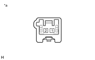
*a Component without harness connected
(Door Unlock Switch Sub-assembly)
Measure the resistance according to the value(s) in the table below.
Standard Resistance Tester Connection Switch Condition Specified Condition 1 - 2 Not turned 10 kΩ or higher 1 - 2 Open position Below 1 Ω Result Proceed to OK NG
NG
REPLACE DOOR UNLOCK SWITCH SUB-ASSEMBLY Click here
OK
-
-
CHECK HARNESS AND CONNECTOR (MAIN BODY ECU (MULTIPLEX NETWORK BODY ECU) - DOOR UNLOCK SWITCH SUB-ASSEMBLY AND BODY GROUND)
-
Disconnect the K11 main body ECU (multiplex network body ECU) connector.
-
Disconnect the X4 door unlock switch sub-assembly connector.
-
Measure the resistance according to the value(s) in the table below.
Standard Resistance Tester Connection Condition Specified Condition K11-23 (TKUL) - X4-2 Always Below 1 Ω X4-1 - Body ground Always Below 1 Ω K11-23 (TKUL) or X4-2 - Body ground Always 10 kΩ or higher Result Proceed to OK NG
OK
REPLACE MAIN BODY ECU (MULTIPLEX NETWORK BODY ECU) Click here
NG
REPAIR OR REPLACE HARNESS OR CONNECTOR
-
-
OPERATION INSPECTION
-
Confirm the problem symptoms.
Result Result Proceed to The luggage compartment door does not operate properly. A The luggage compartment door does not operate properly when the luggage compartment door lock cylinder is operated. B The luggage compartment door does not operate properly when the luggage electrical key switch is operated. C
B
READ VALUE USING GTS Click here
C
GO TO ENTRY AND START SYSTEM (for Entry Function) Click here
A
-
-
READ VALUE USING GTS
-
Connect the GTS to the DLC3.
-
Turn the engine switch on (IG).
-
Turn the GTS on.
-
Enter the following menus: Body Electrical > Back Door > Data List.
-
Read the Data List according to the display on the GTS.
Body Electrical > Back Door > Data ListTester Display Measurement Item Range Normal Condition Diagnostic Note Half Latch SW Luggage door closer assembly (half switch signal) OFF or ON OFF: Half switch of luggage door closer assembly off
ON: Half switch of luggage door closer assembly on
See "Luggage Compartment Door Closer Operation Timing Chart"* Pawl Position Switch Luggage door closer assembly (pawl switch signal) OFF or ON OFF: Pawl switch of luggage door closer assembly off
ON: Pawl switch of luggage door closer assembly on
See "Luggage Compartment Door Closer Operation Timing Chart"*
Body Electrical > Back Door > Data ListTester Display Half Latch SW Pawl Position Switch
-
*: See "Luggage Compartment Door Closer Operation Timing Chart"
OK On the GTS screen, each item changes between ON and OFF as shown in above chart. Result Proceed to OK NG -
OK
REPLACE LUGGAGE DOOR CLOSER ASSEMBLY Click here
NG
-
-
CHECK HARNESS AND CONNECTOR (MULTIPLEX NETWORK DOOR ECU - BATTERY AND BODY GROUND)
-
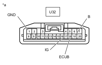
*a Front view of wire harness connector
(to Multiplex Network Door ECU)
Disconnect the multiplex network door ECU connector.
-
Measure the resistance according to the value(s) in the table below.
Standard Resistance Tester Connection Condition Specified Condition U32-1 (GND) - Body ground Always Below 1 Ω -
Measure the voltage according to the value(s) in the table below.
Standard Voltage Tester Connection Switch Condition Specified Condition U32-16 (IG) - Body ground Engine switch on (IG) 11 to 14 V U32-18 (ECUB) - Body ground Always 11 to 14 V U32-19 (B) - Body ground Always 11 to 14 V Result Proceed to OK NG
NG
REPAIR OR REPLACE HARNESS OR CONNECTOR
OK
-
-
INSPECT LUGGAGE DOOR CLOSER ASSEMBLY
-
Remove the luggage door closer assembly.
-
Inspect the luggage door closer assembly
Result Proceed to OK NG
NG
REPLACE LUGGAGE DOOR CLOSER ASSEMBLY Click here
OK
-
-
CHECK HARNESS AND CONNECTOR (MULTIPLEX NETWORK DOOR ECU - LUGGAGE DOOR CLOSER ASSEMBLY)
-
Disconnect the U32 multiplex network door ECU connector.
-
Disconnect the X9 luggage door closer assembly connector.
-
Measure the resistance according to the value(s) in the table below.
Standard Resistance Tester Connection Condition Specified Condition U32-4 (CSV) - X9-3 (CPS+) Always Below 1 Ω U32-5 (CS1) - X9-2 (CPS1) Always Below 1 Ω U32-6 (LCM+) - X9-8 (M+) Always Below 1 Ω U32-7 (LCM-) - X9-1 (M-) Always Below 1 Ω U32-8 (SWG) - X9-7 (E) Always Below 1 Ω U32-8 (SWG) - X9-12 (CSWE) Always Below 1 Ω U32-9 (CSG) - X9-4 (CPSE) Always Below 1 Ω U32-13 (HAF) - X9-6 (FSW) Always Below 1 Ω U32-14 (PAWL) - X9-11 (CLS) Always Below 1 Ω U32-17 (CS2) - X9-9 (CPS2) Always Below 1 Ω U32-4 (CSV) or X9-3 (CPS+) - Body ground Always 10 kΩ or higher U32-5 (CS1) or X9-2 (CPS1) - Body ground Always 10 kΩ or higher U32-6 (LCM+) or X9-8 (M+) - Body ground Always 10 kΩ or higher U32-7 (LCM-) or X9-1 (M-) - Body ground Always 10 kΩ or higher U32-8 (SWG) or X9-7 (E) - Body ground Always 10 kΩ or higher U32-8 (SWG) or X9-12 (CSWE) - Body ground Always 10 kΩ or higher U32-9 (CSG) or X9-4 (CPSE) - Body ground Always 10 kΩ or higher U32-13 (HAF) or X9-6 (FSW) - Body ground Always 10 kΩ or higher U32-14 (PAWL) or X9-11 (CLS) - Body ground Always 10 kΩ or higher U32-17 (CS2) or X9-9 (CPS2) - Body ground Always 10 kΩ or higher Result Proceed to OK NG
NG
REPAIR OR REPLACE HARNESS OR CONNECTOR
OK
-
-
CHECK LUGGAGE DOOR CLOSER ASSEMBLY
-
Replace the luggage door closer assembly with a new or known good one.
-
Check the luggage compartment door closer operation.
OK Luggage compartment door closer normal operation. Result Proceed to OK NG
OK
END (LUGGAGE DOOR CLOSER ASSEMBLY WAS DEFECTIVE)
NG
REPLACE MULTIPLEX NETWORK DOOR ECU Click here
-
-
READ VALUE USING GTS
-
Connect the GTS to the DLC3.
-
Turn the engine switch on (IG).
-
Turn the GTS on.
-
Enter the following menus: Body Electrical > Main Body > Data List.
-
Read the Data List according to the display on the GTS.
Body Electrical > Main Body > Data ListTester Display Measurement Item Range Normal Condition Diagnostic Note Trunk Lock/Unlock SW Door unlock switch signal ON or OFF ON: Luggage compartment door lock cylinder in unlock position
OFF: Luggage compartment door lock cylinder in neutral position
-
Body Electrical > Main Body > Data ListTester Display Trunk Lock/Unlock SW OK On the GTS screen, each item changes between ON and OFF as shown in above chart. Result Proceed to OK NG
OK
REPLACE MAIN BODY ECU (MULTIPLEX NETWORK BODY ECU) Click here
NG
-
-
INSPECT DOOR UNLOCK SWITCH SUB-ASSEMBLY
-
Remove the door unlock switch sub-assembly.
-
*a Component without harness connected
(Door Unlock Switch Sub-assembly)
Measure the resistance according to the value(s) in the table below.
Standard Resistance Tester Connection Switch Condition Specified Condition 1 - 2 Not turned 10 kΩ or higher 1 - 2 Open position Below 1 Ω Result Proceed to OK NG
NG
REPLACE DOOR UNLOCK SWITCH SUB-ASSEMBLY Click here
OK
-
-
CHECK HARNESS AND CONNECTOR (MAIN BODY ECU (MULTIPLEX NETWORK BODY ECU) - DOOR UNLOCK SWITCH SUB-ASSEMBLY AND BODY GROUND)
-
Disconnect the K11 main body ECU (multiplex network body ECU) connector.
-
Disconnect the X4 door unlock switch sub-assembly connector.
-
Measure the resistance according to the value(s) in the table below.
Standard Resistance Tester Connection Condition Specified Condition K11-23 (TKUL) - X4-2 Always Below 1 Ω X4-1 - Body ground Always Below 1 Ω K11-23 (TKUL) or X4-2 - Body ground Always 10 kΩ or higher Result Proceed to OK NG
OK
REPLACE MAIN BODY ECU (MULTIPLEX NETWORK BODY ECU) Click here
NG
REPAIR OR REPLACE HARNESS OR CONNECTOR
-