INSTRUMENT PANEL SAFETY PAD INSTALLATION
CAUTION / NOTICE / HINT
Tech Tips
-
Use the same procedure as for the LHD and RHD vehicles.
-
The procedure listed below is for the LHD vehicles.
PROCEDURE
-
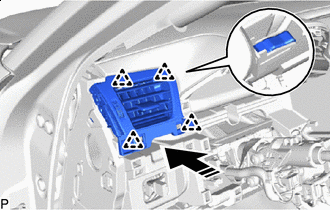
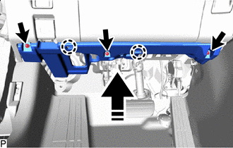
INSTALL INSTRUMENT PANEL SAFETY PAD SUB-ASSEMBLY
-
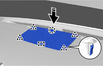
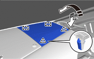
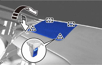
Engage the guides to install the instrument panel safety pad sub-assembly as shown in the illustration.
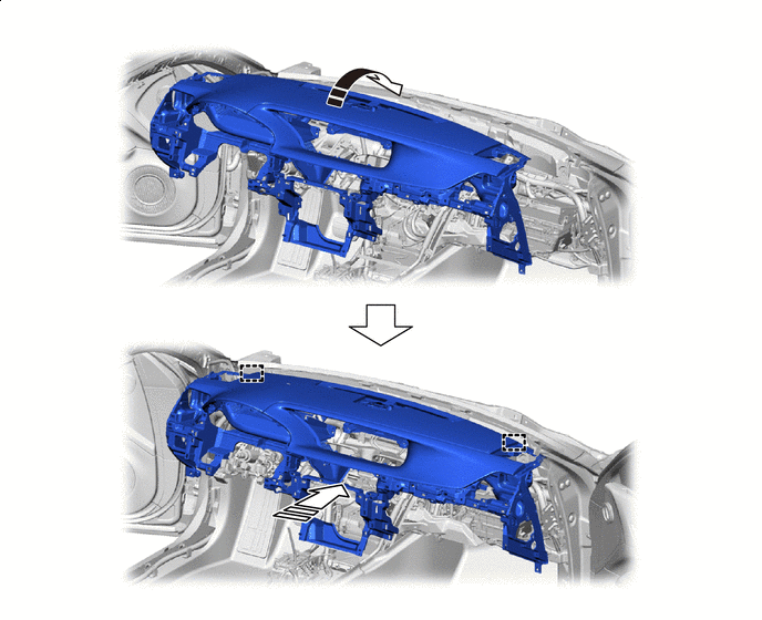

Install in this Direction (1) 
Install in this Direction (2) -
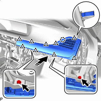
Engage the clamps.
-
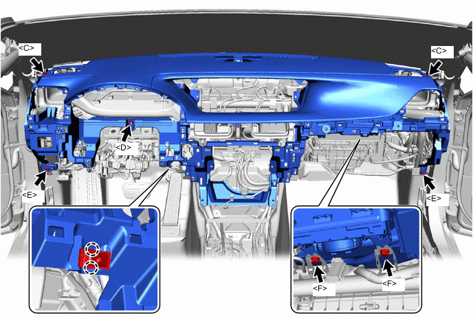
Connect the connectors.
-
Engage the claws to connect the room temperature sensor.
-
Install the 2 bolts <F>.
- Torque:
- 20 N*m { 204 kgf*cm, 15 ft.*lbf }
-
Install the 2 bolts <E>.
-
Install the 2 bolts <C>.
-
Install the nut <D>.
-
-
INSTALL ACCESSORY METER ASSEMBLY (for 12.3 Inch Display)
-
INSTALL MULTI-DISPLAY (for 8 Inch Display)
-
INSTALL INSTRUMENT UPPER CLUSTER FINISH PANEL (for 12.3 Inch Display)
-
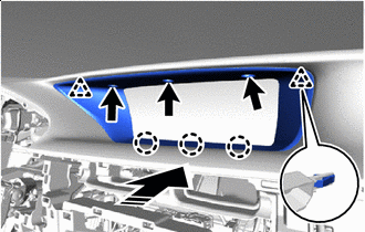
Install in this Direction Engage the claws and clips to install the instrument upper cluster finish panel as shown in the illustration.
-
Install the 3 clips <B>.
-
-
INSTALL INSTRUMENT UPPER CLUSTER FINISH PANEL (for 8 Inch Display)
-
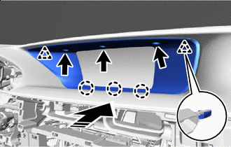
Install in this Direction Engage the claws and clips to install the instrument upper cluster finish panel as shown in the illustration.
-
Install the 3 clips <B>.
-
-
INSTALL NO. 1 SPEAKER WITH BOX ASSEMBLY
-
INSTALL FRONT NO. 3 SPEAKER ASSEMBLY
-
INSTALL FRONT NO. 2 SPEAKER ASSEMBLY
-
INSTALL NO. 1 SPEAKER OPENING COVER ASSEMBLY
-
Install in this Direction Engage the guide, claw and clips to install the No. 1 speaker opening cover assembly as shown in the illustration.
-
-
INSTALL NO. 2 INSTRUMENT PANEL SPEAKER PANEL SUB-ASSEMBLY
-
Install in this Direction (1) Install in this Direction (2) Engage the guides and clips to install the No. 2 instrument panel speaker panel sub-assembly as shown in the illustration.
-
-
INSTALL NO. 1 INSTRUMENT PANEL SPEAKER PANEL SUB-ASSEMBLY
-
Install in this Direction (1) Install in this Direction (2) Engage the guides and clips to install the No. 1 instrument panel speaker panel sub-assembly as shown in the illustration.
-
-
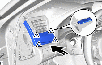
INSTALL NO. 2 INSTRUMENT PANEL GARNISH SUB-ASSEMBLY
-
Connect the connector.
-
Install in this Direction Engage the clips and claw to install the No. 2 instrument panel garnish sub-assembly as shown in the illustration.
-
Install the 2 screws <G>.
-
-
INSTALL NO. 2 INSTRUMENT PANEL REGISTER ASSEMBLY
-
Connect the connectors.
-
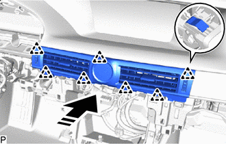
Install in this Direction Engage the clips to install the No. 2 instrument panel register assembly as shown in the illustration.
-
-
INSTALL RADIO RECEIVER ASSEMBLY WITH BRACKET
-
INSTALL GLOVE COMPARTMENT DOOR ASSEMBLY
-
Connect the connectors.
-
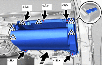
Install in this Direction Engage the clips to install the glove compartment door assembly as shown in the illustration.
-
Install the 2 bolts <E>.
-
Install the 3 screws <A>.
-
-
INSTALL NO. 2 INSTRUMENT PANEL UNDER COVER SUB-ASSEMBLY
-
Connect the connector.
-
Install in this Direction (1) Install in this Direction (2) Engage the guides and clips to install the No. 2 instrument panel under cover sub-assembly as shown in the illustration.
-
-
INSTALL INSTRUMENT SIDE PANEL RH
-
w/ Airbag Cut Off Switch:
-
Connect the connector.
-
-
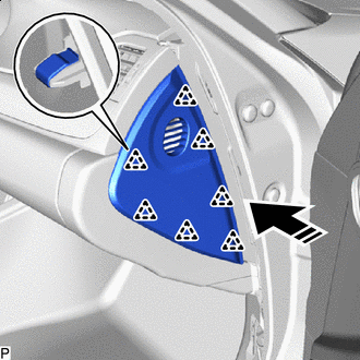
Install in this Direction Engage the clips to install the instrument side panel RH as shown in the illustration.
-
-
INSTALL NO. 1 INSTRUMENT PANEL REGISTER ASSEMBLY
-
Connect the connector.
-
Install in this Direction Engage the clips to install the No. 1 instrument panel register assembly as shown in the illustration.
-
-
INSTALL COMBINATION METER ASSEMBLY
-
INSTALL HEADLIGHT DIMMER SWITCH ASSEMBLY
-
INSTALL INSTRUMENT CLUSTER FINISH PANEL SUB-ASSEMBLY
-
Connect the connectors.
-
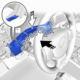
*1 Meter Hood Spacer Install in this Direction (1) Install in this Direction (2) Push in the direction indicated by the arrow (1) in the illustration, engage the clips to install the instrument panel sub-assembly.
-
Push in the direction indicated by the arrow (2) in the illustration, engage the claws to install the meter hood spacer.
-
-
INSTALL INSTRUMENT CLUSTER FINISH PANEL ASSEMBLY
-
Install in this Direction Engage the guides and clips to install the instrument cluster finish panel assembly as shown in the illustration.
-
-
INSTALL LOWER NO. 1 INSTRUMENT PANEL AIRBAG ASSEMBLY
-
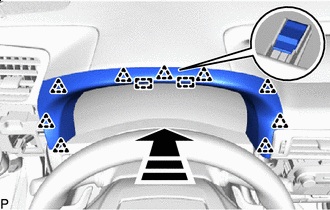
INSTALL NO. 1 INSTRUMENT PANEL SAFETY PAD SUB-ASSEMBLY
-
Connect the connectors.
-
Install in this Direction Engage the guide and clips to install the No. 1 instrument panel safety pad sub-assembly as shown in the illustration.
-
-
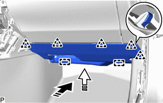
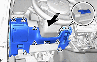
INSTALL NO. 1 INSTRUMENT PANEL UNDER COVER SUB-ASSEMBLY
-
Connect the connector.
-
Install in this Direction Engage the claws to install the No. 1 instrument panel under cover sub-assembly as shown in the illustration.
-
Install the 3 screws <A>.
-
-
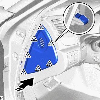
INSTALL NO. 1 INSTRUMENT PANEL GARNISH SUB-ASSEMBLY
-
Install in this Direction Engage the clips to install the No. 1 instrument panel garnish sub-assembly as shown in the illustration.
-
-
INSTALL INSTRUMENT SIDE PANEL LH
-
w/ Airbag Cut Off Switch:
-
Connect the connector.
-
-
Install in this Direction Engage the clips to install the instrument side panel LH as shown in the illustration.
-
-
INSTALL FRONT PILLAR GARNISH LH
-
Remove the adhesive tape and protective cover.
-
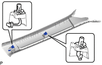
Install the 2 front pillar garnish clips to the front pillar garnish LH.
Note
-
If the front pillar garnish clip has significant damage, replace it with a new one.
-
When installing the front pillar garnish clip, make sure to install it in the correct position and facing in the correct direction.
-
-
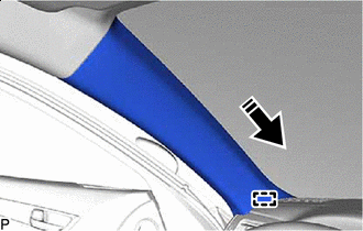
Install in this Direction Engage the guide as shown in the illustration.
-
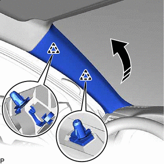
Install in this Direction Engage the clips to install the front pillar garnish LH as shown in the illustration.
-
-
INSTALL FRONT PILLAR GARNISH RH
Tech Tips
Use the same procedure as for the LH side.
-
INSTALL FRONT DOOR OPENING TRIM COVER LH
-
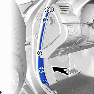
Install in this Direction Engage the claws to install the front door opening trim cover LH as shown in the illustration.
-
-
INSTALL FRONT DOOR OPENING TRIM COVER RH
Tech Tips
Use the same procedure as for the LH side.
-
INSTALL FRONT DOOR SCUFF PLATE LH
-
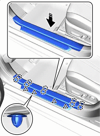
Install in this Direction Engage the clips and claws to install the front door scuff plate LH as shown in the illustration.
-
-
INSTALL FRONT DOOR SCUFF PLATE RH
Tech Tips
Use the same procedure as for the LH side.
-
INSTALL FRONT CONSOLE BOX
-
CONNECT CABLE TO NEGATIVE BATTERY TERMINAL
Note
When disconnecting the cable, some systems need to be initialized after the cable is reconnected.
-
CHECK STEERING WHEEL CENTER POINT
-
INSPECT SRS WARNING LIGHT
-
PERFORM YAW RATE SENSOR AND ROLL RATE AND VERTICAL ACCELERATION SENSOR ZERO POINTS CALIBRATION AND STORE SYSTEM INFORMATION
-
CUSTOMIZE POWER TILT AND POWER TELESCOPIC STEERING COLUMN SYSTEM