INSTRUMENT PANEL SAFETY PAD REASSEMBLY
CAUTION / NOTICE / HINT
Tech Tips
-
Use the same procedure as for the LHD and RHD vehicles.
-
The procedure listed below is for the LHD vehicles.
PROCEDURE
-
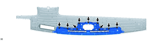
INSTALL NO. 1 DEFROSTER NOZZLE GARNISH (w/ Headup Display)
-
Install the No. 1 defroster nozzle garnish with the 9 screws <A> to the upper instrument panel sub-assembly.
-
-
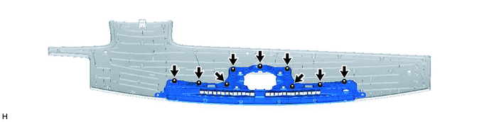
INSTALL NO. 1 DEFROSTER NOZZLE GARNISH (w/o Headup Display)
-
Install the No. 1 defroster nozzle garnish with the 9 screws <A> to the upper instrument panel sub-assembly.
-
-
INSTALL UPPER INSTRUMENT PANEL SUB-ASSEMBLY (w/ Headup Display)
-
Engage the claws to install the upper instrument panel sub-assembly.
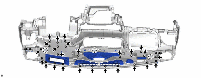
-
Install the 27 screws <A>.
-
-
INSTALL UPPER INSTRUMENT PANEL SUB-ASSEMBLY (w/o Headup Display)
-
Engage the claws to install the upper instrument panel sub-assembly.
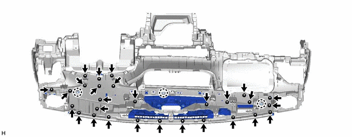
-
Install the 28 screws <A>.
-
-
INSTALL NAVIGATION ANTENNA ASSEMBLY (w/ Navigation System)
-
for LHD:
-
for RHD:
-
-
INSTALL INSTRUMENT PANEL PASSENGER WITHOUT DOOR AIRBAG ASSEMBLY
-
INSTALL NO. 5 INSTRUMENT PANEL WIRE (w/ Headup Display)
-
INSTALL HEADUP DISPLAY (w/ Headup Display)
-
INSTALL AUTOMATIC LIGHT CONTROL SENSOR
-
INSTALL NO. 2 INSTRUMENT PANEL WIRE
-
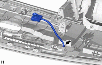
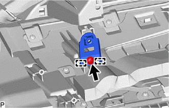
Connect the connector to install the No. 2 instrument panel wire.
-
-
INSTALL SPARE SWITCH HOLE COVER (for RHD)
-
Engage the claws to install the spare switch hole cover.
-
-
INSTALL NO. 5 INSTRUMENT PANEL CUSHION
-
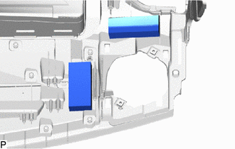
Install 2 new No. 5 instrument panel cushions.
-
-
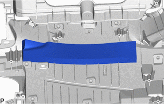
INSTALL NO. 4 INSTRUMENT PANEL CUSHION
-
Install a new No. 4 instrument panel cushion.
-
-
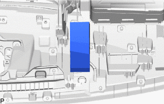
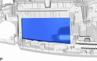
INSTALL NO. 3 INSTRUMENT PANEL CUSHION
-
Install a new No. 3 instrument panel cushion.
-
-
INSTALL NO. 2 INSTRUMENT PANEL CUSHION (w/o Headup Display)
-
Install a new No. 2 instrument panel cushion.
-
-
INSTALL NO. 1 INSTRUMENT PANEL CUSHION
-
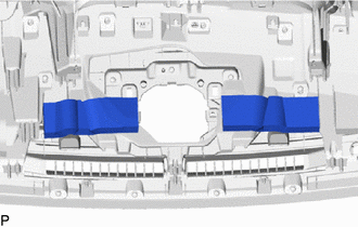
Install 2 new No. 1 instrument panel cushions.
-
-
INSTALL INSTRUMENT PANEL SAFETY PAD RETAINER
-
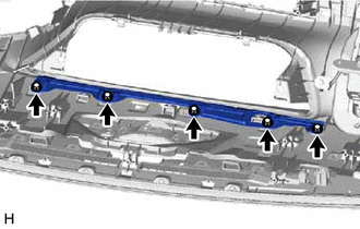
Install the instrument panel safety pad retainer with the 5 screws <A>.
-
-
INSTALL NO. 3 INSTRUMENT PAD BRACKET
Tech Tips
Use the same procedure as for the opposite side.
-
Engage the guides to install the No. 3 instrument pad bracket.
-
Install the screw <A>.
-
-
INSTALL NO. 1 METER HOOD RETAINER
-
Engage the guides to install the No. 1 meter hood retainer.
-
Install the 2 screws <A>.
-
-
INSTALL NO. 1 INSTRUMENT PANEL PIN
-
Engage the guide to install the No. 1 instrument panel pin.
-
Install the screw <A>.
-
-
INSTALL NO. 2 INSTRUMENT PANEL PIN
Tech Tips
Use the same procedure as for the No. 1 side.
-
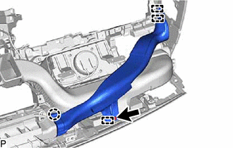
INSTALL NO. 2 HEATER TO REGISTER DUCT
-
Engage the guides to install the No. 2 heater to register duct.
-
Install the 2 screws <F>.
-
-
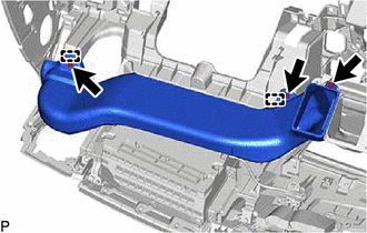
INSTALL NO. 3 HEATER TO REGISTER DUCT
-
Engage the guides to install the No. 3 heater to register duct.
-
Install the 3 screws <F>.
-
-
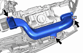
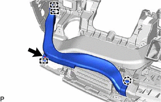
INSTALL NO. 1 HEATER TO REGISTER DUCT
-
Engage the guides to install the No. 1 heater to register duct.
-
Install the 3 screws <F>.
-
-
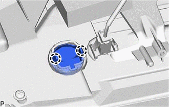
INSTALL DEFROSTER NOZZLE ASSEMBLY
-
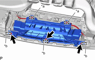
*a Clamp *b Guide Engage the guides to install the defroster nozzle assembly.
-
Install the 3 screws <F>.
-
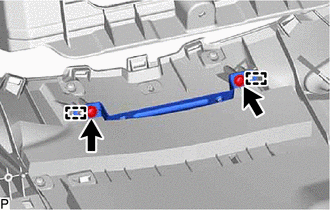
Engage the clamps to connect the wire harness connectors.
-
-
INSTALL NO. 2 SIDE DEFROSTER NOZZLE DUCT
-
Engage the claw and guides to install the No. 2 side defroster nozzle duct.
-
Install the screw <F>.
-
-
INSTALL NO. 1 SIDE DEFROSTER NOZZLE DUCT
-
Engage the claw and guides to install the No. 2 side defroster nozzle duct.
-
Install the screw <F>.
-