REAR SUNSHADE SYSTEM Rear Sunshade Shift-linked Function does not Operate when Shift Lever is Moved to R Position
DESCRIPTION
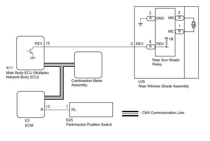
When the engine switch is on (IG) and the rear sunshade is raised, moving the shift lever to R causes the park/neutral position switch to send a reverse-linked signal to the ECM. Then the ECM sends the signal through the CAN communication line to the main body ECU (multiplex network body ECU), which sends the signal to the rear sun shade relay. The rear sun shade relay then lowers the rear sunshade.
Tech Tips
The reverse-linked function of the rear sunshade system only operates when it has been set to "ON" using the customize function of the GTS (the default setting is "ON").
WIRING DIAGRAM
CAUTION / NOTICE / HINT
Note
-
If the main body ECU (multiplex network body ECU) is replaced, refer to the Service Bulletin.
-
Do not remove the ground bolt of the rear window shade assembly.
-
When the rear sun shade relay is replaced with a new one, do not use the wire harness packaged together with the new rear sun shade relay.
Tech Tips
Since the rear sunshade system has functions that use CAN communication, first confirm that there is no malfunction in the communication system by inspecting the CAN communication functions in accordance with the "How to Proceed with Troubleshooting" procedures. Then, conduct the following inspection procedure.
PROCEDURE
-
READ VALUE USING GTS (SHIFT SW STATUS (R RANGE))
-
Connect the GTS to the DLC3.
-
Turn the engine switch on (IG).
-
Turn the GTS on.
-
Enter the following menus: Powertrain > Engine > Data List.
-
Read the Data List according to the display on the GTS.
Powertrain > Engine > Data ListTester Display Measurement Item Range Normal Condition Diagnostic Note Shift SW Status (R Range) Park/neutral position switch status (R Range) ON or OFF
-
ON: Shift lever in R
-
OFF: Shift lever not in R
When the shift lever position displayed on the GTS differs from the actual position, the adjustment of the park/neutral position switch may be incorrect.
Powertrain > Engine > Data ListTester Display Shift SW Status (R Range) OK GTS display changes correctly according to shift lever operation. Result Proceed to OK NG -
NG 
GO TO AUTOMATIC TRANSMISSION SYSTEM Click here
OK 
-
-
PERFORM ACTIVE TEST USING GTS (REVERSE GEAR SIGNAL)
-
Make sure that the rear sunshade lowers.
-
Select the Active Test, use the GTS to generate a control command, and then check that the rear sunshade can be lowered.
OK Rear sunshade can be lowered.
Body Electrical > Main Body > Active TestTester Display Measurement Item Control Range Diagnostic Note Reverse Gear Signal Reverse signal output control ON / OFF -
Body Electrical > Main Body > Active TestTester Display Reverse Gear Signal Result Proceed to OK NG
OK
REPLACE MAIN BODY ECU (MULTIPLEX NETWORK BODY ECU) Click here
NG
-
-
CHECK HARNESS AND CONNECTOR (REAR WINDOW SHADE ASSEMBLY - MAIN BODY ECU (MULTIPLEX NETWORK BODY ECU))
-
Disconnect the U25 rear window shade assembly connector.
-
Disconnect the K11 main body ECU (multiplex network body ECU) connector.
-
Measure the resistance according to the value(s) in the table below.
Standard Resistance Tester Connection Condition Specified Condition U25-3 (REV) - K11-15 (REV) Always Below 1 Ω U25-3 (REV) - Body ground Always 10 kΩ or higher Result Proceed to OK NG
NG
REPAIR OR REPLACE HARNESS OR CONNECTOR
OK
-
-
CHECK REAR WINDOW SHADE ASSEMBLY
-
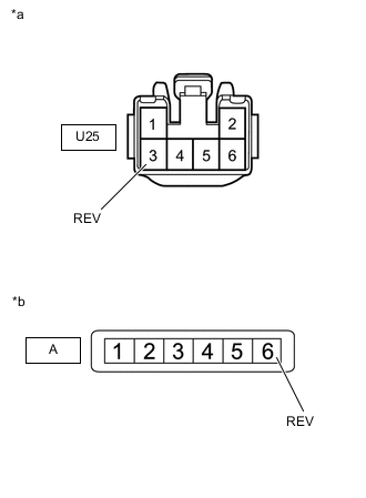
*a Component without harness connected
(Rear Window Shade Assembly)
*b Component without harness connected
(Rear Sun Shade Relay)
Disconnect the rear window shade assembly connector.
-
Disconnect the rear sun shade relay connector.
-
Measure the resistance according to the value(s) in the table below.
Standard Resistance Tester Connection Condition Specified Condition U25-3 (REV) - A-6 (REV) Always Below 1 Ω U25-3 (REV) - Body ground Always 10 kΩ or higher Result Proceed to OK NG
NG
REPLACE REAR WINDOW SHADE ASSEMBLY Click here
OK
-
-
CHECK REAR SUN SHADE RELAY
-
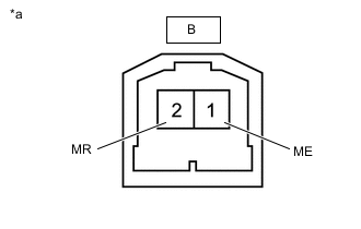
*a Component with harness connected
(Rear Window Shade Assembly)
Measure the voltage according to the value(s) in the table below.
Standard Voltage Tester Connection Condition Specified Condition B-2 (MR) - B-1 (ME) Rear sunshade is fully raised and shift lever is moved from N to R 11 to 14 V Result Proceed to OK NG
OK
REPLACE REAR WINDOW SHADE ASSEMBLY Click here
NG
REPLACE REAR SUN SHADE RELAY Click here
-