POWER WINDOW CONTROL SYSTEM Driver Side Power Window does not Operate with Power Window Master Switch
DESCRIPTION
When the engine switch is on (IG), the power window regulator motor assembly (for driver door) is operated by the power window regulator master switch assembly. The power window regulator motor assembly (for driver door) has motor, regulator and ECU functions.
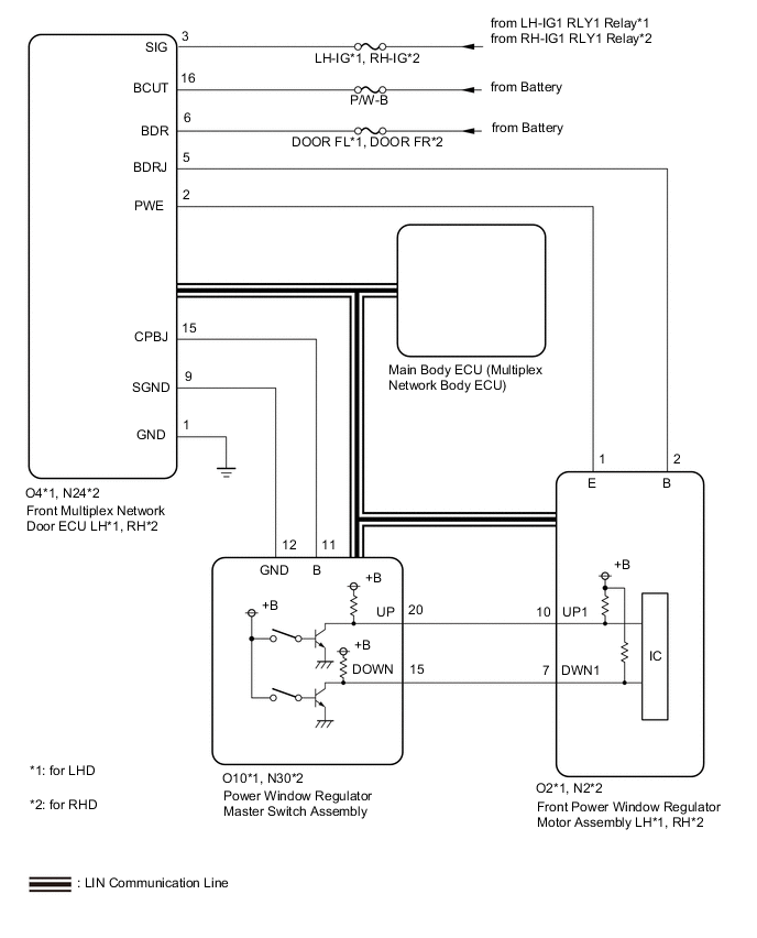
WIRING DIAGRAM
CAUTION / NOTICE / HINT
Note
-
The power window control system uses the LIN communication system. Inspect the communication function by following How to Proceed with Troubleshooting. Troubleshoot the power window control system after confirming that the communication system is functioning properly.
-
If the power window regulator motor assembly (for driver door) has been replaced with a new one, initialize the power window control system.
-
Inspect the fuses for circuits related to this system before performing the following procedure.
-
If the main body ECU (multiplex network body ECU) is replaced, refer to Service Bulletin.
PROCEDURE
-
READ VALUE USING GTS (MAIN BODY)
-
Connect the GTS to the DLC3.
-
Turn the engine switch on (IG).
-
Turn the GTS on.
-
Enter the following menus: Body Electrical / Main Body / Data List.
-
Read the Data List according to the display on the GTS.
Body Electrical > Main Body > Data ListTester Display Measurement Item Range Normal Condition Diagnostic Note Communication D-Door Motor Connection status between power window regulator motor assembly (for driver door) and main body ECU (multiplex network body ECU) STOP or OK STOP: Communication stopped
OK: Normal communication
- Communication Master SW Connection status between power window regulator master switch assembly and main body ECU (multiplex network body ECU) STOP or OK STOP: Communication stopped
OK: Normal communication
-
Body Electrical > Main Body > Data ListTester Display Communication D-Door Motor Communication Master SW OK On the GTS screen, OK is displayed. Result Proceed to OK NG
NG 
GO TO LIN COMMUNICATION SYSTEM Click here
OK 
-
-
READ VALUE USING GTS (D-DOOR MOTOR)
-
Connect the GTS to the DLC3.
-
Turn the engine switch on (IG).
-
Turn the GTS on.
-
Enter the following menus: Body Electrical / D-Door Motor / Data List.
-
Read the Data List according to the display on the GTS.
Body Electrical > D-Door Motor > Data ListTester Display Measurement Item Range Normal Condition Diagnostic Note D Door P/W Up SW Driver door power window manual up switch signal OFF or ON OFF: Driver door power window manual up switch not being operated
ON: Driver door power window manual up switch being operated
- D Door P/W Down SW Driver door power window manual down switch signal OFF or ON OFF: Driver door power window manual down switch not being operated
ON: Driver door power window manual down switch being operated
-
Body Electrical > D-Door Motor > Data ListTester Display D Door P/W Up SW D Door P/W Down SW OK On the GTS screen, ON or OFF is displayed accordingly. Result Result Proceed to OK A NG (for LHD) B NG (for RHD) C
B 
CHECK HARNESS AND CONNECTOR (FRONT MULTIPLEX NETWORK DOOR ECU LH - BATTERY AND BODY GROUND) Click here
C
CHECK HARNESS AND CONNECTOR (FRONT MULTIPLEX NETWORK DOOR ECU RH - BATTERY AND BODY GROUND) Click here
A
-
-
PERFORM ACTIVE TEST USING GTS (D-DOOR MOTOR)
-
Connect the GTS to the DLC3.
-
Turn the engine switch on (IG).
-
Turn the GTS on.
-
Enter the following menus: Body Electrical / D-Door Motor / Active Test.
-
Perform the Active Test according to the display on the GTS.
CAUTION:
Be careful to avoid injuries as this test causes vehicle parts to move. During the Active Test, the jam protection function will not operate.
Body Electrical > D-Door Motor > Active TestTester Display Measurement Item Control Range Diagnostic Note Power Window Power window OFF / DOWN / UP -
Body Electrical > D-Door Motor > Active TestTester Display Power Window OK Driver door power window operates normally. Result Proceed to OK NG
OK
REPLACE POWER WINDOW REGULATOR MASTER SWITCH ASSEMBLY Click here
NG
REPLACE POWER WINDOW REGULATOR MOTOR ASSEMBLY (FOR DRIVER DOOR) Click here
-
-
CHECK HARNESS AND CONNECTOR (FRONT MULTIPLEX NETWORK DOOR ECU LH - BATTERY AND BODY GROUND)
-
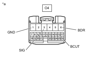
*a Front view of wire harness connector
(to Front Multiplex Network Door ECU LH)
Disconnect the front multiplex network door ECU LH connector.
-
Measure the voltage and resistance according to the value(s) in the table below.
Standard Voltage Tester Connection Switch Condition Specified Condition O4-6 (BDR) - O4-1 (GND) Always 11 to 14 V O4-16 (BCUT) - O4-1 (GND) Always 11 to 14 V O4-3 (SIG) - O4-1 (GND) Engine switch on (IG) 11 to 14 V Standard Resistance Tester Connection Condition Specified Condition O4-1 (GND) - Body ground Always Below 1 Ω Result Proceed to OK NG
NG
REPAIR OR REPLACE HARNESS OR CONNECTOR
OK
-
-
CHECK HARNESS AND CONNECTOR (POWER WINDOW REGULATOR MASTER SWITCH ASSEMBLY - FRONT MULTIPLEX NETWORK DOOR ECU LH)
-
Disconnect the O10 power window regulator master switch assembly connector.
-
Disconnect the O4 front multiplex network door ECU LH connector.
-
Measure the resistance according to the value(s) in the table below.
Standard Resistance Tester Connection Condition Specified Condition O10-11 (B) - O4-15 (CPBJ) Always Below 1 Ω O10-12 (GND) - O4-9 (SGND) Always Below 1 Ω O10-11 (B) - Body ground Always 10 kΩ or higher O10-12 (GND) - Body ground Always 10 kΩ or higher Result Proceed to OK NG
NG
REPAIR OR REPLACE HARNESS OR CONNECTOR
OK
-
-
CHECK HARNESS AND CONNECTOR (FRONT POWER WINDOW REGULATOR MOTOR ASSEMBLY LH - FRONT MULTIPLEX NETWORK DOOR ECU LH)
-
Disconnect the O2 front power window regulator motor assembly LH connector.
-
Disconnect the O4 front multiplex network door ECU LH connector.
-
Measure the resistance according to the value(s) in the table below.
Standard Resistance Tester Connection Condition Specified Condition O2-2 (B) - O4-5 (BDRJ) Always Below 1 Ω O2-1 (E) - O4-2 (PWE) Always Below 1 Ω O2-2 (B) - Body ground Always 10 kΩ or higher O2-1 (E) - Body ground Always 10 kΩ or higher Result Proceed to OK NG
NG
REPAIR OR REPLACE HARNESS OR CONNECTOR
OK
-
-
CHECK FRONT MULTIPLEX NETWORK DOOR ECU LH
-
Measure the voltage according to the value(s) in the table below.
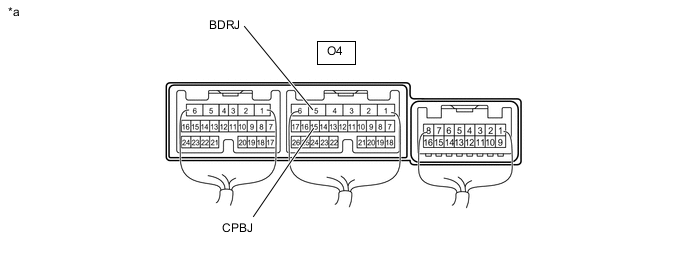
*a Component with harness connected
(Front Multiplex Network Door ECU LH)
- - Standard Voltage Tester Connection Condition Specified Condition O4-5 (BDRJ) - Body ground Always 11 to 14 V O4-15 (CPBJ) - Body ground Always 11 to 14 V Result Proceed to OK NG
NG
REPLACE FRONT MULTIPLEX NETWORK DOOR ECU LH Click here
OK
-
-
INSPECT FRONT MULTIPLEX NETWORK DOOR ECU LH
-
Remove the front multiplex network door ECU LH.
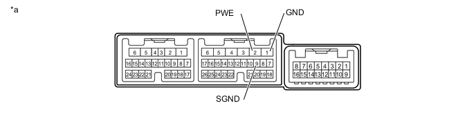
*a Component without harness connected
(Front multiplex Network Door ECU LH)
- - -
Measure the resistance according to the value(s) in the table below.
Standard Resistance Tester Connection Condition Specified Condition 2 (PWE) - 1 (GND) Always Below 1 Ω 9 (SGND) - 1 (GND) Always Below 1 Ω Result Proceed to OK NG
NG
REPLACE FRONT MULTIPLEX NETWORK DOOR ECU LH Click here
OK
-
-
CHECK HARNESS AND CONNECTOR (POWER WINDOW REGULATOR MASTER SWITCH ASSEMBLY - FRONT POWER WINDOW REGULATOR MOTOR ASSEMBLY LH)
-
Disconnect the O10 power window regulator master switch assembly connector.
-
Disconnect the O2 front power window regulator motor assembly LH connector.
-
Measure the resistance according to the value(s) in the table below.
Standard Resistance Tester Connection Condition Specified Condition O10-20 (UP) - O2-10 (UP1) Always Below 1 Ω O10-15 (DOWN) - O2-7 (DWN1) Always Below 1 Ω O10-20 (UP) - Body ground Always 10 kΩ or higher O10-15 (DOWN) - Body ground Always 10 kΩ or higher Result Proceed to OK NG
NG
REPAIR OR REPLACE HARNESS OR CONNECTOR
OK
-
-
INSPECT FRONT POWER WINDOW REGULATOR MOTOR ASSEMBLY LH
-
Remove the front power window regulator motor assembly LH.
-
Inspect the front power window regulator motor assembly LH.
Result Proceed to OK NG
OK
REPLACE POWER WINDOW REGULATOR MASTER SWITCH ASSEMBLY Click here
NG
REPLACE FRONT POWER WINDOW REGULATOR MOTOR ASSEMBLY LH Click here
-
-
CHECK HARNESS AND CONNECTOR (FRONT MULTIPLEX NETWORK DOOR ECU RH - BATTERY AND BODY GROUND)
-
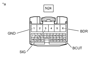
*a Front view of wire harness connector
(to Front Multiplex Network Door ECU RH)
Disconnect the front multiplex network door ECU RH connector.
-
Measure the voltage and resistance according to the value(s) in the table below.
Standard Voltage Tester Connection Switch Condition Specified Condition N24-6 (BDR) - N24-1 (GND) Always 11 to 14 V N24-16 (BCUT) - N24-1 (GND) Always 11 to 14 V N24-3 (SIG) - N24-1 (GND) Engine switch on (IG) 11 to 14 V Standard Resistance Tester Connection Condition Specified Condition N24-1 (GND) - Body ground Always Below 1 Ω Result Proceed to OK NG
NG
REPAIR OR REPLACE HARNESS OR CONNECTOR
OK
-
-
CHECK HARNESS AND CONNECTOR (POWER WINDOW REGULATOR MASTER SWITCH ASSEMBLY - FRONT MULTIPLEX NETWORK DOOR ECU RH)
-
Disconnect the N30 power window regulator master switch assembly connector.
-
Disconnect the N24 front multiplex network door ECU RH connector.
-
Measure the resistance according to the value(s) in the table below.
Standard Resistance Tester Connection Condition Specified Condition N30-11 (B) - N24-15 (CPBJ) Always Below 1 Ω N30-12 (GND) - N24-9 (SGND) Always Below 1 Ω N30-11 (B) - Body ground Always 10 kΩ or higher N30-12 (GND) - Body ground Always 10 kΩ or higher Result Proceed to OK NG
NG
REPAIR OR REPLACE HARNESS OR CONNECTOR
OK
-
-
CHECK HARNESS AND CONNECTOR (FRONT POWER WINDOW REGULATOR MOTOR ASSEMBLY RH - FRONT MULTIPLEX NETWORK DOOR ECU RH)
-
Disconnect the N2 front power window regulator motor assembly RH connector.
-
Disconnect the N24 front multiplex network door ECU RH connector.
-
Measure the resistance according to the value(s) in the table below.
Standard Resistance Tester Connection Condition Specified Condition N2-2 (B) - N24-5 (BDRJ) Always Below 1 Ω N2-1 (E) - N24-2 (PWE) Always Below 1 Ω N2-2 (B) - Body ground Always 10 kΩ or higher N2-1 (E) - Body ground Always 10 kΩ or higher Result Proceed to OK NG
NG
REPAIR OR REPLACE HARNESS OR CONNECTOR
OK
-
-
CHECK FRONT MULTIPLEX NETWORK DOOR ECU RH
-
Measure the voltage according to the value(s) in the table below.
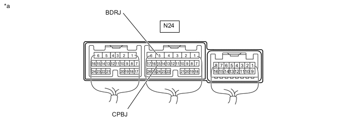
*a Component with harness connected
(Front Multiplex Network Door ECU LH)
- - Standard Voltage Tester Connection Condition Specified Condition N24-5 (BDRJ) - Body ground Always 11 to 14 V N24-15 (CPBJ) - Body ground Always 11 to 14 V Result Proceed to OK NG
NG
REPLACE FRONT MULTIPLEX NETWORK DOOR ECU RH Click here
OK
-
-
INSPECT FRONT MULTIPLEX NETWORK DOOR ECU RH
-
Remove the front multiplex network door ECU RH.

*a Component without harness connected
(Front Multiplex Network Door ECU RH)
- - -
Measure the resistance according to the value(s) in the table below.
Standard Resistance Tester Connection Condition Specified Condition 2 (PWE) - 1 (GND) Always Below 1 Ω 9 (SGND) - 1 (GND) Always Below 1 Ω Result Proceed to OK NG
NG
REPLACE FRONT MULTIPLEX NETWORK DOOR ECU RH Click here
OK
-
-
CHECK HARNESS AND CONNECTOR (POWER WINDOW REGULATOR MASTER SWITCH ASSEMBLY - FRONT POWER WINDOW REGULATOR MOTOR ASSEMBLY RH)
-
Disconnect the N30 power window regulator master switch assembly connector.
-
Disconnect the N2 front power window regulator motor assembly RH connector.
-
Measure the resistance according to the value(s) in the table below.
Standard Resistance Tester Connection Condition Specified Condition N30-20 (UP) - N2-10 (UP1) Always Below 1 Ω N30-15 (DOWN) - N2-7 (DWN1) Always Below 1 Ω N30-20 (UP) - Body ground Always 10 kΩ or higher N30-15 (DOWN) - Body ground Always 10 kΩ or higher Result Proceed to OK NG
NG
REPAIR OR REPLACE HARNESS OR CONNECTOR
OK
-
-
INSPECT FRONT POWER WINDOW REGULATOR MOTOR ASSEMBLY RH
-
Remove the front power window regulator motor assembly RH.
-
Inspect the front power window regulator motor assembly RH.
Result Proceed to OK NG
OK
REPLACE POWER WINDOW REGULATOR MASTER SWITCH ASSEMBLY Click here
NG
REPLACE FRONT POWER WINDOW REGULATOR MOTOR ASSEMBLY RH Click here
-