AIR CONDITIONING SYSTEM, Diagnostic DTC:B1413/13
| DTC Code | DTC Name |
|---|---|
| B1413/13 | Evaporator Temperature Sensor Circuit |
DESCRIPTION
The No. 1 cooler thermistor (evaporator temperature sensor) is installed on the evaporator in the air conditioner unit to detect the temperature of the air that has passed through the evaporator and is used to control the air conditioning. It sends signals to the air conditioning amplifier assembly. The resistance of the No. 1 cooler thermistor (evaporator temperature sensor) changes in accordance with the cooled air temperature that has passed through the evaporator. As the temperature decreases, the resistance increases. As the temperature increases, the resistance decreases.
The air conditioning amplifier assembly applies voltage (5 V) to the No. 1 cooler thermistor (evaporator temperature sensor) and reads voltage changes as the resistance of the No. 1 cooler thermistor changes. This sensor is used for frost prevention.
| DTC No. | Detection Item | DTC Detection Condition | Trouble Area | Memory |
|---|---|---|---|---|
| B1413/13 | Evaporator Temperature Sensor Circuit | Any of the following conditions is met:
|
|
Memorized (4 seconds or more) |
Tech Tips
The air conditioning amplifier assembly stores the DTC of the respective malfunction if it has occurred for the period of time indicated in the brackets.
| Vehicle Condition | |||
|---|---|---|---|
| Pattern 1 | Pattern 2 | ||
| Diagnosis Condition | Engine switch to on (IG) | ○ | ○ |
| Malfunction Status | Open in No. 1 cooler thermistor (evaporator temperature sensor) circuit | ○ | - |
| Short in No. 1 cooler thermistor (evaporator temperature sensor) circuit | - | ○ | |
| Detection Time | 4 seconds or more | 4 seconds or more | |
| Number of Trips | 1 trip | 1 trip | |
Tech Tips
DTC will be output when conditions for either of the patterns in the table above are met.
WIRING DIAGRAM
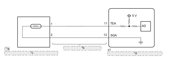
| *a | ae |
| *b | Air Conditioning Harness Assembly |
| *c | No. 1 Cooler Thermistor (Evaporator Temperature Sensor) |
| *d | Air Conditioning Amplifier Assembly |
CAUTION / NOTICE / HINT
Note
Before disconnecting the cable from the negative (-) battery terminal or replacing the air conditioning amplifier assembly, record the last operation state of the air conditioning for each transmitter. After replacement, it is necessary to perform memory registration for each transmitter.
PROCEDURE
-
READ VALUE USING GTS
-
Connect the GTS to the DLC3.
-
Turn the engine switch to on (IG).
-
Turn the GTS on.
-
Enter the following menus: Body Electrical / Air Conditioner / Data List.
-
Check the value(s) by referring to the table below.
Body Electrical > Air Conditioner > Data ListTester Display Measurement Item Range Normal Condition Diagnostic Note Evaporator Fin Thermistor No. 1 cooler thermistor (evaporator temperature sensor) Min.: -29.70°C (-21.46°F)
Max.: 59.55°C (139.19°F)
Actual evaporator temperature displayed -
Body Electrical > Air Conditioner > Data ListTester Display Evaporator Fin Thermistor OK The display is as specified in the normal condition column. Result Result Proceed to OK (When troubleshooting according to Problem Symptoms Table) A OK (When troubleshooting according to the DTC) B NG C
A 
PROCEED TO NEXT SUSPECTED AREA SHOWN IN PROBLEM SYMPTOMS TABLE Click here
B
REPLACE AIR CONDITIONING AMPLIFIER ASSEMBLY Click here
C 
-
-
INSPECT NO. 1 COOLER THERMISTOR (EVAPORATOR TEMPERATURE SENSOR)
-
Remove the No. 1 cooler thermistor (evaporator temperature sensor).
-
Inspect the No. 1 cooler thermistor (evaporator temperature sensor).
Result Proceed to OK NG
NG
REPLACE NO. 1 COOLER THERMISTOR (EVAPORATOR TEMPERATURE SENSOR) Click here
OK
-
-
CHECK AIR CONDITIONING HARNESS ASSEMBLY
-
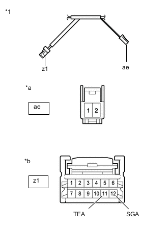
*1 Air Conditioning Harness Assembly *a Front view of air conditioning harness assembly
(to No. 1 Cooler Thermistor (Evaporator Temperature Sensor))
*b Front view of air conditioning harness assembly
(to Air Conditioning Amplifier Assembly)
Disconnect the air conditioning harness assembly connector.
-
Measure the resistance according to the value(s) in the table below.
Standard Resistance Tester Connection Condition Specified Condition z1-11 (TEA) - ae-1 Always Below 1 Ω z1-12 (SGA) - ae-2 Always Below 1 Ω z1-11 (TEA) or ae-1 - Body ground Always 10 kΩ or higher z1-12 (SGA) or ae-2 - Body ground Always 10 kΩ or higher Result Proceed to OK NG
OK
REPLACE AIR CONDITIONING AMPLIFIER ASSEMBLY Click here
NG
REPLACE AIR CONDITIONING HARNESS ASSEMBLY Click here
-