AIR CONDITIONING SYSTEM, Diagnostic DTC:B1497/97
| DTC Code | DTC Name |
|---|---|
| B1497/97 | BUS IC Communication Malfunction |
DESCRIPTION
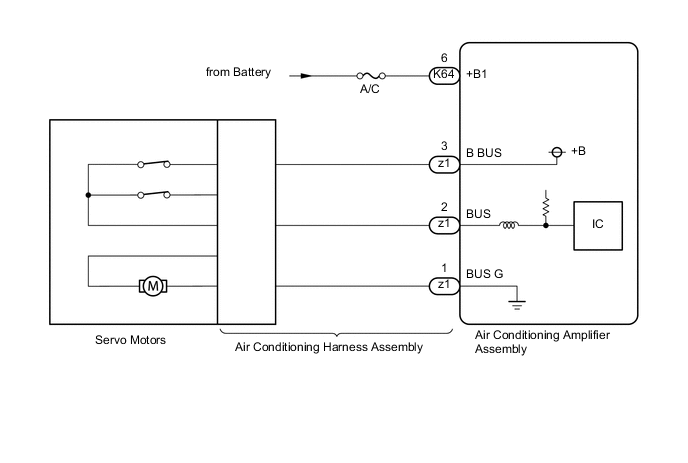
The air conditioning harness assembly connects the air conditioning amplifier assembly and the servo motors. The air conditioning amplifier assembly supplies power and sends operation instructions to each servo motor through the air conditioning harness assembly. Each servo motor sends damper position information to the air conditioning amplifier assembly.
| DTC No. | Detection Item | DTC Detection Condition | Trouble Area | Memory |
|---|---|---|---|---|
| B1497/97 | BUS IC Communication Malfunction | Any of the following conditions is met:
|
|
Memorized (10 seconds or more) |
-
*1: w/ Rear Control Switch
-
*2: for LHD
-
*3: for RHD
Tech Tips
The air conditioning amplifier assembly stores this DTC if the malfunction has occurred for the period of time indicated in the brackets.
| Vehicle Condition | |||
|---|---|---|---|
| Pattern 1 | Pattern 2 | ||
| Diagnosis Condition | Engine switch to on (IG) | ○ | ○ |
| Malfunction Status | Error in communication line | ○ | - |
| Open in communication line | - | ○ | |
| Detection Time | 10 seconds or more | 10 seconds or more | |
| Number of Trips | 1 trip | 1 trip | |
Tech Tips
DTC will be output when conditions for either of the patterns in the table above are met.
WIRING DIAGRAM
CAUTION / NOTICE / HINT
Note
-
Inspect the fuses for circuits related to this system before performing the following procedure.
-
Before disconnecting the cable from the negative (-) battery terminal or replacing the air conditioning amplifier assembly, record the last operation state of the air conditioning for each transmitter. After replacement, it is necessary to perform memory registration for each transmitter.
PROCEDURE
-
PERFORM ACTIVE TEST USING GTS
-
Connect the GTS to the DLC3.
-
Turn the engine switch on (IG).
-
Turn the GTS on.
-
Enter the following menus: Body Electrical / Air Conditioner / Active Test.
-
Check the operation by referring to the table below.
Body Electrical > Air Conditioner > Active TestTester Display Measurement Item Control Range Diagnostic Note Air Mix Servo Targ Pulse(D) No. 2 air conditioning radiator damper servo sub-assembly (driver side air mix) Min.: 128
Max.: 383
Operates between 254 to 360 pulses*2
Operates between 152 to 258 pulses*3
Air Mix Servo Targ Pulse(P) No. 2 air conditioning radiator damper servo sub-assembly (front passenger side air mix) Min.: 128
Max.: 383
Operates between 152 to 258 pulses*2
Operates between 254 to 360 pulses*3
Air Outlet Servo Pulse (D) No. 6 air conditioning radiator damper servo sub-assembly*4 or No. 5 air conditioning radiator damper servo sub-assembly*5 Min.: 128
Max.: 383
Operates between 140 to 254 pulses*4
Operates between 258 to 372 pulses*5
Air Inlet Damper Targ Pulse No. 1 blower damper servo sub-assembly Min.: 128
Max.: 383
Operates between 206 to 238 pulses*2
Operates between 274 to 306 pulses*3
Rear Air Mix Servo Targ Pulse No. 3 air conditioning radiator damper servo sub-assembly (rear air mix)*1 Min.: 128
Max.: 383
Operates between 254 to 360 pulses Air Outlet Servo Pulse (P) No. 5 air conditioning radiator damper servo sub-assembly*6 or No. 6 air conditioning radiator damper servo sub-assembly*5 Min.: 128
Max.: 383
Operates between 258 to 372 pulses*6
Operates between 140 to 254 pulses*5
Cool A/M Servo Pulse(D) No. 4 air conditioning radiator damper servo sub-assembly*2 or No. 3 air conditioning radiator damper servo sub-assembly (driver side lower)*3 Min.: 128
Max.: 383
Operates between 254 to 360 pulses Cool A/M Servo Pulse(P) No. 3 air conditioning radiator damper servo sub-assembly (front passenger side lower)*2 or No. 4 air conditioning radiator damper servo sub-assembly*3 Min.: 128
Max.: 383
Operates between 254 to 360 pulses A/O Servo Pulse(Rr D) No. 7 air conditioning radiator damper servo sub-assembly Min.: 128
Max.: 383
Operates between 242 to 353 pulses DEF A/O Servo Pulse(D) No. 1 air conditioning radiator damper servo sub-assembly Min.: 128
Max.: 383
Operates between 164 to 270 pulses
-
*1: w/ Rear Control Switch
-
*2: for LHD
-
*3: for RHD
-
*4: for LHD or RHD without Rear Control Switch
-
*5: for RHD with Rear Control Switch
-
*6: for LHD with Rear Control Switch
Body Electrical > Air Conditioner > Active TestTester Display Air Mix Servo Targ Pulse(D)
Body Electrical > Air Conditioner > Active TestTester Display Air Mix Servo Targ Pulse(P)
Body Electrical > Air Conditioner > Active TestTester Display Air Outlet Servo Pulse (D)
Body Electrical > Air Conditioner > Active TestTester Display Air Outlet Servo Pulse (P)
Body Electrical > Air Conditioner > Active TestTester Display Air Inlet Damper Targ Pulse
Body Electrical > Air Conditioner > Active TestTester Display Cool A/M Servo Pulse(D)
Body Electrical > Air Conditioner > Active TestTester Display Cool A/M Servo Pulse(P)
Body Electrical > Air Conditioner > Active TestTester Display A/O Servo Pulse(Rr D)
Body Electrical > Air Conditioner > Active TestTester Display Rear Air Mix Servo Targ Pulse
Body Electrical > Air Conditioner > Active TestTester Display DEF A/O Servo Pulse(D) OK Damper servo motors signal changes according to the target pulse specified by the Active Test. -
-
According to the test result, proceed to the next step.
Result Result Proceed to One of the damper servo motors is malfunctioning (air mix damper servo motor) A One of the damper servo motors is malfunctioning (air outlet damper servo motor) B Only the No. 1 blower damper servo sub-assembly is malfunctioning C All of the damper servo motors are malfunctioning D
B 
SYSTEM CHECK Click here
C
REPLACE NO. 1 BLOWER DAMPER SERVO SUB-ASSEMBLY Click here
D
REPLACE AIR CONDITIONING HARNESS ASSEMBLY Click here
A 
-
-
SYSTEM CHECK
-
According to the test result, proceed to the next step.
Result Result Proceed to Only the No. 2 air conditioning radiator damper servo sub-assembly (driver side air mix) is malfunctioning A Only the No. 2 air conditioning radiator damper servo sub-assembly (front passenger side air mix) is malfunctioning B Only the No. 3 air conditioning radiator damper servo sub-assembly (front passenger side lower)*1 or No. 3 air conditioning radiator damper servo sub-assembly (driver side lower)*2 is malfunctioning C Only the No. 4 air conditioning radiator damper servo sub-assembly is malfunctioning D Only the No. 3 air conditioning radiator damper servo sub-assembly (rear air mix) is malfunctioning*3 E
-
*1: for LHD
-
*2: for RHD
-
*3: w/ Rear Control Switch
-
B
REPLACE NO. 2 AIR CONDITIONING RADIATOR DAMPER SERVO SUB-ASSEMBLY (FRONT PASSENGER SIDE AIR MIX) Click here
C
REPLACE NO. 3 AIR CONDITIONING RADIATOR DAMPER SERVO SUB-ASSEMBLY (FRONT PASSENGER SIDE LOWER) OR NO. 3 AIR CONDITIONING RADIATOR DAMPER SERVO SUB-ASSEMBLY (DRIVER SIDE LOWER) Click here
D
REPLACE NO. 4 AIR CONDITIONING RADIATOR DAMPER SERVO SUB-ASSEMBLY Click here
E
REPLACE NO. 3 AIR CONDITIONING RADIATOR DAMPER SERVO SUB-ASSEMBLY (REAR AIR MIX) Click here
A
-
-
REPLACE NO. 2 AIR CONDITIONING RADIATOR DAMPER SERVO SUB-ASSEMBLY (DRIVER SIDE AIR MIX)
-
Replace the No. 2 air conditioning radiator damper servo sub-assembly (driver side air mix).
Tech Tips
Since the servo motor cannot be inspected while it is removed from the vehicle, replace the servo motor with a new or known good one and check that the condition returns to normal.
-
Check for DTCs.
Body Electrical > Air Conditioner > Trouble CodesResult Result Proceed to DTC B1497/97 is not output A DTC B1497/97 is output B
A 
END (NO. 2 AIR CONDITIONING RADIATOR DAMPER SERVO SUB-ASSEMBLY [DRIVER SIDE AIR MIX] WAS DEFECTIVE)
B
GO TO STEP 14 Click here
-
-
REPLACE NO. 2 AIR CONDITIONING RADIATOR DAMPER SERVO SUB-ASSEMBLY (FRONT PASSENGER SIDE AIR MIX)
-
Replace the No. 2 air conditioning radiator damper servo sub-assembly (front passenger side air mix).
Tech Tips
Since the servo motor cannot be inspected while it is removed from the vehicle, replace the servo motor with a new or known good one and check that the condition returns to normal.
-
Check for DTCs.
Body Electrical > Air Conditioner > Trouble CodesResult Result Proceed to DTC B1497/97 is not output A DTC B1497/97 is output B
A
END (NO. 2 AIR CONDITIONING RADIATOR DAMPER SERVO SUB-ASSEMBLY [FRONT PASSENGER SIDE AIR MIX] WAS DEFECTIVE)
B
GO TO STEP 14 Click here
-
-
REPLACE NO. 3 AIR CONDITIONING RADIATOR DAMPER SERVO SUB-ASSEMBLY (FRONT PASSENGER SIDE LOWER) OR NO. 3 AIR CONDITIONING RADIATOR DAMPER SERVO SUB-ASSEMBLY (DRIVER SIDE LOWER)
-
Replace the No. 3 air conditioning radiator damper servo sub-assembly (front passenger side lower)*1 or No. 3 air conditioning radiator damper servo sub-assembly (driver side lower)*2.
Tech Tips
Since the servo motor cannot be inspected while it is removed from the vehicle, replace the servo motor with a new or known good one and check that the condition returns to normal.
-
*1: for LHD
-
*2: for RHD
-
-
Check for DTCs.
Body Electrical > Air Conditioner > Trouble CodesResult Result Proceed to DTC B1497/97 is not output (for LHD) A DTC B1497/97 is not output (for RHD) B DTC B1497/97 is output C
A
END (NO. 3 AIR CONDITIONING RADIATOR DAMPER SERVO SUB-ASSEMBLY [FRONT PASSENGER SIDE LOWER] WAS DEFECTIVE)
B
END (NO. 3 AIR CONDITIONING RADIATOR DAMPER SERVO SUB-ASSEMBLY [DRIVER SIDE LOWER] WAS DEFECTIVE)
C
GO TO STEP 14 Click here
-
-
REPLACE NO. 4 AIR CONDITIONING RADIATOR DAMPER SERVO SUB-ASSEMBLY
-
Replace the No. 4 air conditioning radiator damper servo sub-assembly.
Tech Tips
Since the servo motor cannot be inspected while it is removed from the vehicle, replace the servo motor with a new or known good one and check that the condition returns to normal.
-
Check for DTCs.
Body Electrical > Air Conditioner > Trouble CodesResult Result Proceed to DTC B1497/97 is not output A DTC B1497/97 is output B
A
END (NO. 4 AIR CONDITIONING RADIATOR DAMPER SERVO SUB-ASSEMBLY WAS DEFECTIVE)
B
GO TO STEP 14 Click here
-
-
REPLACE NO. 3 AIR CONDITIONING RADIATOR DAMPER SERVO SUB-ASSEMBLY (REAR AIR MIX)
-
Replace the No. 3 air conditioning radiator damper servo sub-assembly (rear air mix).
Tech Tips
Since the servo motor cannot be inspected while it is removed from the vehicle, replace the servo motor with a new or known good one and check that the condition returns to normal.
-
Check for DTCs.
Body Electrical > Air Conditioner > Trouble CodesResult Result Proceed to DTC B1497/97 is not output A DTC B1497/97 is output B
A
END (NO. 3 AIR CONDITIONING RADIATOR DAMPER SERVO SUB-ASSEMBLY [REAR AIR MIX] WAS DEFECTIVE)
B
GO TO STEP 14 Click here
-
-
SYSTEM CHECK
-
According to the test result, proceed to the next step.
Result Result Proceed to Only the No. 1 air conditioning radiator damper servo sub-assembly is malfunctioning A Only the No. 6 air conditioning radiator damper servo sub-assembly is malfunctioning B Only the No. 5 air conditioning radiator damper servo sub-assembly is malfunctioning* C Only the No. 7 air conditioning radiator damper servo sub-assembly is malfunctioning D
-
*: w/ Rear Control Switch
-
B
REPLACE NO. 5 AIR CONDITIONING RADIATOR DAMPER SERVO SUB-ASSEMBLY Click here
C
REPLACE NO. 6 AIR CONDITIONING RADIATOR DAMPER SERVO SUB-ASSEMBLY Click here
D
REPLACE NO. 7 AIR CONDITIONING RADIATOR DAMPER SERVO SUB-ASSEMBLY Click here
A
-
-
REPLACE NO. 1 AIR CONDITIONING RADIATOR DAMPER SERVO SUB-ASSEMBLY
-
Replace the No. 1 air conditioning radiator damper servo sub-assembly.
Tech Tips
Since the servo motor cannot be inspected while it is removed from the vehicle, replace the servo motor with a new or a known good one and check that the condition returns to normal.
-
Check for DTCs.
Result Result Proceed to DTC B1497/97 is not output A DTC B1497/97 is output B
A
END (NO. 1 AIR CONDITIONING RADIATOR DAMPER SERVO SUB-ASSEMBLY WAS DEFECTIVE)
B
GO TO STEP 14 Click here
-
-
REPLACE NO. 5 AIR CONDITIONING RADIATOR DAMPER SERVO SUB-ASSEMBLY
-
Replace the No. 5 air conditioning radiator damper servo sub-assembly.
Tech Tips
Since the servo motor cannot be inspected while it is removed from the vehicle, replace the servo motor with a new or a known good one and check that the condition returns to normal.
-
Check for DTCs.
Result Result Proceed to DTC B1497/97 is not output A DTC B1497/97 is output B
A
END (NO. 5 AIR CONDITIONING RADIATOR DAMPER SERVO SUB-ASSEMBLY WAS DEFECTIVE)
B
GO TO STEP 14 Click here
-
-
REPLACE NO. 6 AIR CONDITIONING RADIATOR DAMPER SERVO SUB-ASSEMBLY
-
Replace the No. 6 air conditioning radiator damper servo sub-assembly.
Tech Tips
Since the servo motor cannot be inspected while it is removed from the vehicle, replace the servo motor with a new or a known good one and check that the condition returns to normal.
-
Check for DTCs.
Result Result Proceed to DTC B1497/97 is not output A DTC B1497/97 is output B
A
END (NO. 6 AIR CONDITIONING RADIATOR DAMPER SERVO SUB-ASSEMBLY WAS DEFECTIVE)
B
GO TO STEP 14 Click here
-
-
REPLACE NO. 7 AIR CONDITIONING RADIATOR DAMPER SERVO SUB-ASSEMBLY
-
Replace the No. 7 air conditioning radiator damper servo sub-assembly.
Tech Tips
Since the servo motor cannot be inspected while it is removed from the vehicle, replace the servo motor with a new or known good one and check that the condition returns to normal.
-
Check for DTCs.
Body Electrical > Air Conditioner > Trouble CodesResult Result Proceed to DTC B1497/97 is not output A DTC B1497/97 is output B
A
END (NO. 7 AIR CONDITIONING RADIATOR DAMPER SERVO SUB-ASSEMBLY WAS DEFECTIVE)
B
GO TO STEP 14 Click here
-
-
REPLACE NO. 1 BLOWER DAMPER SERVO SUB-ASSEMBLY
-
Replace the No. 1 blower damper servo sub-assembly.
Tech Tips
Since the servo motor cannot be inspected while it is removed from the vehicle, replace the servo motor with a new or known good one and check that the condition returns to normal.
-
Check for DTCs.
Body Electrical > Air Conditioner > Trouble CodesResult Result Proceed to DTC B1497/97 is not output A DTC B1497/97 is output B
A
END (NO. 1 BLOWER DAMPER SERVO SUB-ASSEMBLY WAS DEFECTIVE)
B
-
-
REPLACE AIR CONDITIONING HARNESS ASSEMBLY
-
Replace the air conditioning harness assembly.
Tech Tips
Since the air conditioning harness assembly cannot be inspected while it is removed from the vehicle, replace the air conditioning harness assembly with a new or known good one and check that the condition returns to normal.
-
Check for DTCs.
Body Electrical > Air Conditioner > Trouble CodesResult Result Proceed to DTC B1497/97 is not output A DTC B1497/97 is output B
A
END (AIR CONDITIONING HARNESS ASSEMBLY WAS DEFECTIVE)
B
-
-
CHECK HARNESS AND CONNECTOR (POWER SOURCE CIRCUIT)
-
Disconnect the K64 air conditioning amplifier assembly connector.
-
Measure the voltage according to the value(s) in the table below.
Standard Voltage Tester Connection Condition Specified Condition K64-6 (+B1) - Body ground Always 11 to 14 V Result Proceed to OK NG
OK
REPLACE AIR CONDITIONING AMPLIFIER ASSEMBLY Click here
NG
REPAIR OR REPLACE HARNESS OR CONNECTOR
-