AIR CONDITIONING SYSTEM SYSTEM DESCRIPTION
-
GENERAL
-
The air conditioning system consists of the following parts:
Component Function Radio Receiver Assembly Allows operation and adjustment of the air conditioning system via switches. Accessory Meter Assembly*1 Multi-display*2 Remote Touch
-
Remote Operation Switch
-
Remote Operation Board
Rear Control Switch*3 Allows operation and adjustment of the rear air conditioning via switches. Air Conditioning Amplifier Assembly Transmits and receives data to and from the switches and sensors, and controls the air conditioning system. Compressor with Pulley Assembly Performs suction, compression and discharge of refrigerant gas. Blower Motor with Fan Sub-assembly Controls the blower motor with fan sub-assembly in accordance with the airflow volume that has been calculated by the neural network control based on the input signals from various sensors. Cooler Condenser Assembly A Global Inner-fin Condenser (GIC) is used to improve heat exchange efficiency. Heater Radiator Unit Sub-assembly A Straight Flow Aluminum-II (SFA-II) heater radiator is used for compactness and high performance. No. 1 Cooler Evaporator Sub-assembly A Revolutionary super-slim Structure (RS) type cooler evaporator subassembly is used for compactness and high performance. No. 1 Cooler Thermistor Detects the temperature of the cool air past the cooler evaporator sub-assembly and transmits the data to the air conditioning amplifier assembly. Thermistor Assembly Detects ambient temperature and outputs it to the air conditioning amplifier assembly. Cooler Thermistor Detects room temperature and outputs it to the air conditioning amplifier assembly. Smog Ventilation Sensor*4 Detects harmful elements such as CO, HC, and NOx, which are present in the air outside of the vehicle and outputs this information to the air conditioning amplifier assembly. Automatic Light Control Sensor Detects changes in the amount of solar energy and outputs them to the air conditioning amplifier assembly. Liquid Pipe Sub-assembly
-
Air Conditioning Pressure Sensor
Detects the refrigerant pressure and sends data to the air conditioning amplifier assembly. Combination Switch Assembly Sends the ECO switch operation signal to the air conditioning amplifier assembly. Damper Servo Sub-assembly Receives the operation signals from the air conditioning amplifier assembly, operates the motor, and opens and closes the dampers. ECM Sends data to and receives data from the air conditioning amplifier assembly via CAN communication. Power Steering ECU Assembly Sends data to and receives data from the air conditioning amplifier assembly via CAN communication. Certification ECU (Smart Key ECU Assembly) Sends data to and receives data from the air conditioning amplifier assembly via CAN communication. Main Body ECU (Multiplex Network Body ECU) Sends data to and receives data from the air conditioning amplifier assembly via CAN communication. Combination Meter Assembly Sends data to and receives data from the air conditioning amplifier assembly via CAN communication. Network Gateway ECU Relays and transmits each CAN communication data signal.
-
*1: for 12.3 Inch
-
*2: for 8 Inch
-
*3: w/ Rear Control Switch
-
*4: w/ Smog Ventilation Sensor
-
-
Control List
Control Function Neural Network Control This control is capable of effecting complex control by artificially simulating the information processing method of the nervous system of living organisms in order to establish a complex input/output relationship that is similar to a human brain. Automatic Recirculation Control*3 Automatically changes the air inlet mode to fresh air or recirculate mode according to the level of harmful elements in the outside air, cabin temperature, and outside temperature. Micro Dust and Pollen Filter Mode Control
-
Activated by the micro dust and pollen filter mode switch operation.
-
Sends air which has passed through the air refiner element to the area around the upper part of the bodies of the driver and front passenger. This air has been filtered by the air refiner element in order to remove pollen.
Outlet Air Temperature Control Based on the temperature set at the temperature control switch, the neural network control calculates the outlet air temperature based on the input signals from various sensors. The temperature setting for the driver, front passenger and rear passenger is controlled independently in order to provide a separate vehicle interior temperature for the right, left and rear sides of the vehicle. Thus, air conditioning control that accommodates different occupant preferences has been achieved.*1 The temperature setting for the driver and front passenger is controlled independently in order to provide a separate vehicle interior temperature for the right and left sides of the vehicle. Thus, air conditioning control that accommodates different occupant preferences has been achieved.*2 Blower Control Controls the blower motor in accordance with the airflow volume that has been calculated by neural network control based on the input signals from various sensors. Automatically increases the blower level when the defroster is on. Air Outlet Control Automatically switches the air outlets in accordance with the outlet mode that has been calculated by neural network control based on the input signals from various sensors. In accordance with the engine coolant temperature, outside air temperature, amount of sunlight, required blower, outlet temperature and vehicle speed conditions, this control automatically switches the blower outlet to FOOT/DEF mode to prevent the windows from becoming fogged when the outside air temperature is low. S-FLOW Control Front seat air outlet mode is turned on when the driver is the only occupant in the cabin and the conditions are satisfied by the signals from each sensor. In addition, driver seat air outlet mode is turned on when the cabin condition stabilizes. Air Inlet Control Automatically controls the air inlet control damper to achieve the calculated outlet air temperature that is required. Drives the No. 1 blower damper servo sub-assembly (fresh/recirculation damper) in accordance with the operation of the air inlet control switch and moves the dampers to the FRESH or RECIRC position. Compressor Control The air conditioning amplifier assembly calculates the target speed of the compressor based on the target evaporator temperature (which is calculated by the cooler thermistor, thermistor assembly and automatic light control sensor) and the actual evaporator temperature that is detected by the No. 1 cooler thermistor in order to control the compressor speed. Turns the air conditioning on automatically by pressing the AUTO switch when the blower is on and the air conditioning is off. Evaporator Control When set to automatic, cooler compressor variable capacity operation is controlled to save power. When set to manual, cooler compressor variable capacity operation is controlled for maximum cooling to dehumidify air and prevent the windows from fogging up. Memory Call Control Memorizes the last air conditioning settings when the engine switch is turned from on (IG) to off in accordance with the ID code of the electrical key transmitter sub-assembly that is used to operate the vehicle. The memory call control then recalls the settings if the electrical key transmitter sub-assembly is used when the engine switch is turned on (IG). This function operates when both of the following conditions are met:
-
Inside of the outside door handle is touched or the driver door is unlocked using the unlock button, and then the driver door is opened.
-
Engine switch is turned on (IG).
-
*1: w/ Rear Control Switch
-
*2: w/o Rear Control Switch
-
*3: w/ Smog Ventilation Sensor
-
-
-
MODE POSITION AND DAMPER OPERATION
-
Mode Position and Damper Operation.
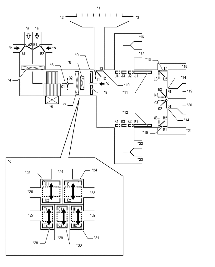
*1 Front Defroster Duct *2 Driver Side Defroster Duct *3 Front Passenger Side Defroster Duct *4 Air Refiner Element *5 Blower Motor with Fan Sub-assembly *6 Inside-and-outside Dual Air Layer Control Door *7 No. 1 Cooler Evaporator Sub-assembly *8 No. 1 Heater Radiator Unit Sub-assembly *9 Air Mix Control Door *10 Mode Control Door (for Defroster) *11 Mode Control Door (for Driver Center and Side Register) *12 Mode Control Door (for Front Passenger Center and Side Register) *13 Mode Control Door (for Driver Footwell Register) *14 Mode Control Door (for Console Box Register Duct and Rear Footwell Register Duct) *15 Mode Control Door (for Front Passenger Footwell Register) *16 Driver Side Register Duct *17 Driver Side Center Register Duct *18 Driver Side Footwell Register Duct *19 Console Box Register Duct *20 Rear Footwell Register Duct *21 Front Passenger Side Footwell Register Duct *22 Front Passenger Side Center Register Duct *23 Front Passenger Side Register Duct *24 To Center and Side Defrosters *25 Air Mix Control Door (for Driver Side Upper Layer) *26 To Driver Side Center and Side Registers *27 To Driver Side Footwell Register Duct *28 Air Mix Control Door (for Driver Side Lower Layer) *29 To Console Box Register Duct and Rear Footwell Register Duct *30 Air Mix Control Door (for Rear Passenger) *31 Air Mix Control Door (for Front Passenger Lower Layer) *32 To Front Passenger Side Footwell Register Duct *33 To Front Passenger Side Center and Side Register *34 Air Mix Control Door (for Front Passenger Side Upper Layer) *a Recirculated Air *b Fresh Air *c A View *d View from A Mode Position and Door Operation Control Door Operation Position*1 Damper Position Operation Air Inlet Control Door FRESH A2, B1 Brings in fresh air. RECIRCULATION A1, B2 Recirculates internal air. Inside-and-outside Dual Air Layer Control Door - (Auto Control) C1 - C2 Separates or integrates the upper layer and lower layer in response to the control conditions to control the inside-and-outside dual air layers. Air Mix Control Door MAX COLD to MAX HOT Temperature Setting D1 - D2*2
E1 - E2*3
F1 - F2*4
G1 - G2*5
H1 - H2*6
Varies the mixture ratio of warm air and cool air in order to continuously regulate the temperature between hot and cold. Mode Control Door (for All Seat Control Modes) FACE J1, K1, L1, M1, N3, O1, I3, I2*7 Air blows out of the center register, side register and console box register. BI-LEVEL J2, K2, L2, M2, N2, O2, I3, I2*7 Air blows out of the center register, side register, console box register and front and rear footwell register ducts. Air may blow out from the center defroster and side defroster depending on the cabin environment (I2). FOOT J3, K3, L3, M3, N2, O3, I2 Air blows out of the front footwell register and rear footwell register ducts. In addition, air blows out slightly from the center register, side register and console box register. Air blows out slightly from the center defroster and side defroster. FOOT AND DEFROSTER J3, K3, L2, M2, N2, O2, I1 Defrosts the windshield through the center defroster and side defroster, while air is also blown out from the front footwell register and rear footwell register ducts. In addition, air blows out slightly from the center register, side register and console box register. DEFROSTER J4, K4, L1, M1, N1, O1, I1 Defrosts the windshield through the center defroster and side defroster ducts. Mode Control Door (for Front Seat Control Modes)*8 FACE J1, K1, L1, M1, N3, O1, I3, I2*7 Air blows out of the center register and side register. BI-LEVEL J2, K2, L2, M2, N1, O2, I3, I2*7 Air blows out of the center register, side register and front footwell register ducts. Air may blow out from the center defroster and side defroster depending on the cabin environment (I2). FOOT J3, K3, L3, M3, N1, O1, I2 Air blows out of the front footwell register. In addition, air blows out slightly from the front center register and side register. Air blows out slightly from the center defroster and side defroster. FOOT AND DEFROSTER J3, K3, L2, M2, N1, O1, I1 Defrosts the windshield through the center defroster and side defroster, while air is also blown out from the front footwell register. In addition, air blows out slightly from the center register and side. DEFROSTER J4, K4, L1, M1, N1, O1, I1 Defrosts the windshield through the center defroster and side defroster ducts. Mode Control Door (for Driver Seat Control Modes)*9 FACE J1, K1, L1, M1, N3, O1, I3, I2*7 Air blows out of the driver side center register and side register. BI-LEVEL J2, K4, L2, M1, N1, O1, I3, I2*7 Air blows out of the driver side center register, side register and front footwell register ducts. FOOT J3, K4, L3, M1, N1, O1, I2 Air blows out of the driver side front footwell register. In addition, air blows out slightly from the driver side center register and side register. Air blows out slightly from the center defroster and side defroster. FOOT AND DEFROSTER J3, K4, L2, M1, N1, O1, I1 Defrosts the windshield through the center defroster and side defroster, while air is also blown out from the driver side front footwell register. In addition, air blows out slightly from the driver side center register and side register.
-
*1: The table shows the left and right air outlets and rear seat air outlets operating simultaneously.
On the models with 3-zone temperature control, each seat air outlet can be switched independently.
-
*2: For driver side center register and side register
-
*3: For front passenger side center register and side register
-
*4: For driver side footwell register
-
*5: For console box register and rear footwell register ducts
-
*6: For front passenger side footwell register
-
*7: On models for Europe, when the volume of air from the center register and side register is large, air blows out slightly from the center defroster and side defroster.
-
*8: When the rear seat air outlets are stopped by the left and right independent temperature control, or when front seat control mode is turned on through the S-FLOW control of the 3-zone temperature control.
-
*9: The driver seat control mode is turned on by the S-FLOW control of the 3-zone temperature control.
-
-
-
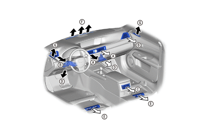
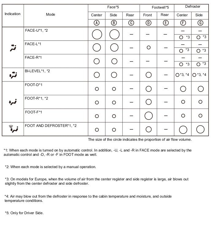
AIR OUTLETS AND AIRFLOW VOLUME
-
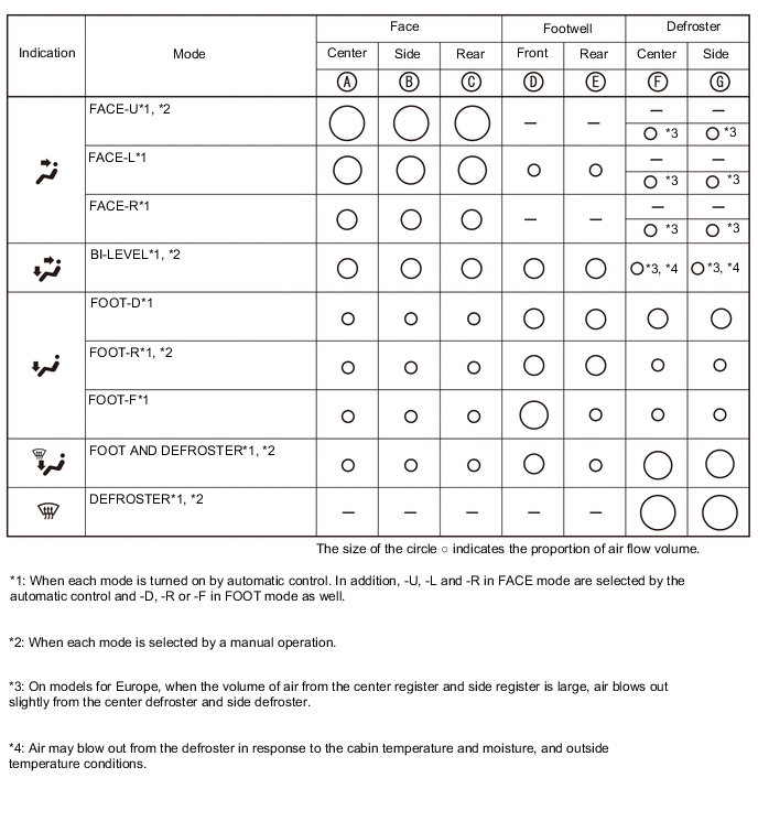
Air Outlets and Airflow Volume (for All Seat Control Modes)
-
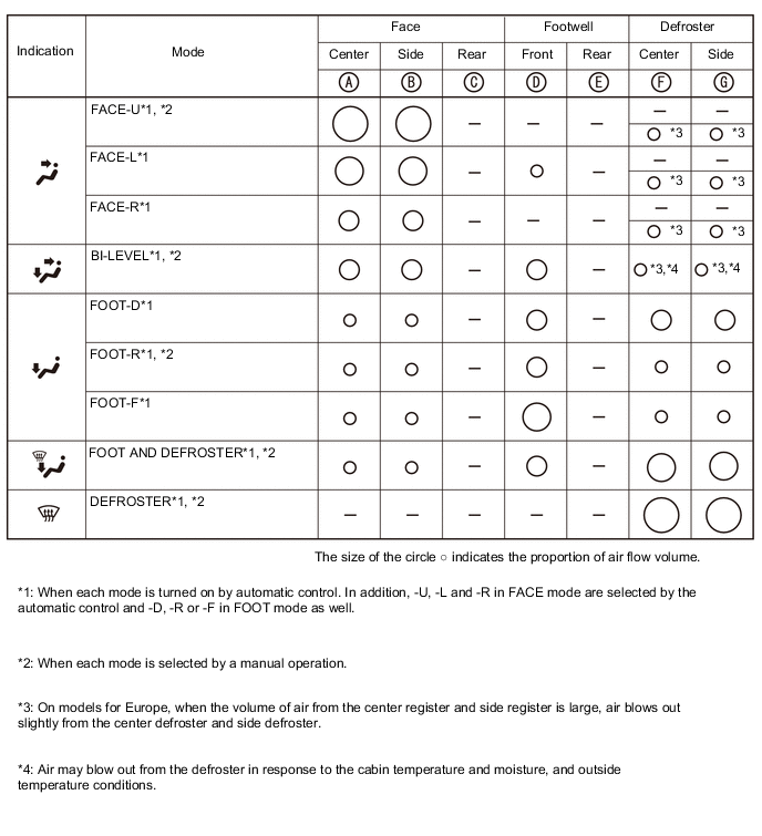
Air Outlets and Airflow Volume (for Front Seat Control Modes)

-
Air Outlets and Airflow Volume (for Driver Seat Control Modes)
-