AIR CONDITIONING UNIT REASSEMBLY
PROCEDURE
-
INSTALL HEATER CASE SUB-ASSEMBLY
-
Engage the 10 claws to install a new heater case sub-assembly.
-
-
INSTALL NO. 1 COOLER THERMISTOR
-
INSTALL NO. 1 COOLER EVAPORATOR SUB-ASSEMBLY
-
Sufficiently apply compressor oil to 2 new O-rings and the fitting surfaces of the No. 1 cooler evaporator sub-assembly.
Compressor Oil for HFC-134a (R134a) ND-OIL 8 or equivalent for HFO-1234yf (R1234yf) ND-OIL 12 or equivalent -
Install the 2 O-rings to the No. 1 cooler evaporator sub-assembly.
Note
Keep the O-rings and O-ring fitting surfaces free of foreign matter.
-
Install the No. 1 cooler evaporator sub-assembly to the air duct as shown in the illustration.
-
Engage the claws to install the air duct.
-
Install the 5 screws.
-
-
INSTALL NO. 2 AIR CONDITIONING RADIATOR DAMPER SERVO SUB-ASSEMBLY (for LH Side)
-
*a Reference Point Using the reference point, install the No. 2 air conditioning radiator damper servo sub-assembly with the 2 screws.
-
-
INSTALL NO. 4 AIR CONDITIONING RADIATOR DAMPER SERVO SUB-ASSEMBLY
-
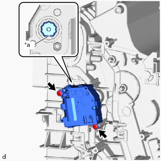
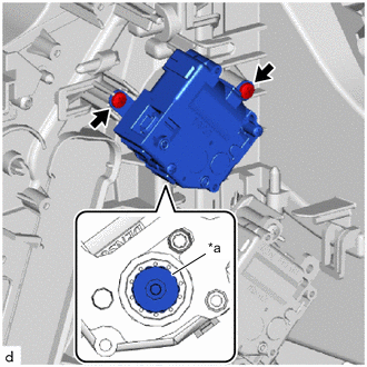
*a Reference Point Using the reference points, install the No. 4 air conditioning radiator damper servo sub-assembly with the 2 screws.
-
-
INSTALL NO. 6 AIR CONDITIONING RADIATOR DAMPER SERVO SUB-ASSEMBLY
-
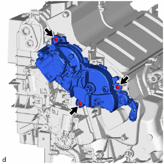
Install the No. 6 air conditioning radiator damper servo sub-assembly with the 3 screws.
Note
Make sure that each link guide pin of the No. 6 air conditioning radiator damper servo sub-assembly are inserted in each guide hole of the air conditioning radiator assembly.
-
-
INSTALL NO. 7 AIR CONDITIONING RADIATOR DAMPER SERVO SUB-ASSEMBLY
-
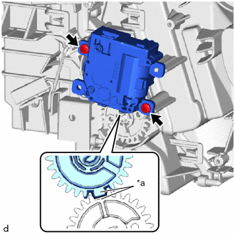
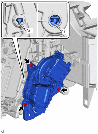
*a Reference Point Using the reference points, install the No. 7 air conditioning radiator damper servo sub-assembly with the 2 screws.
-
-
INSTALL NO. 5 AIR CONDITIONING RADIATOR DAMPER SERVO SUB-ASSEMBLY (for 3 Zone Type)
-
Install the No. 5 air conditioning radiator damper servo sub-assembly with the 3 screws.
Note
Make sure that each link guide pin of the No. 5 air conditioning radiator damper servo sub-assembly are inserted in each guide hole of the air conditioning radiator assembly.
-
-
INSTALL NO. 3 AIR CONDITIONING RADIATOR DAMPER SERVO SUB-ASSEMBLY
-
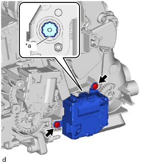
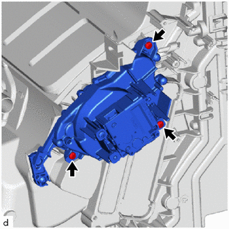
*a Reference Point Using the reference points, install the No. 3 air conditioning radiator damper servo sub-assembly with the 3 screws.
-
-
INSTALL NO. 2 AIR CONDITIONING RADIATOR DAMPER SERVO SUB-ASSEMBLY (for RH Side)
-
*a Reference Point Using the reference point, install the No. 2 air conditioning radiator damper servo sub-assembly with the 2 screws.
-
-
INSTALL NO. 1 AIR CONDITIONING RADIATOR DAMPER SERVO SUB-ASSEMBLY
-
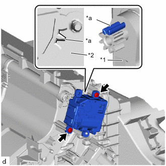
*1 No. 1 Air Conditioning Radiator Damper Servo Sub-assembly *2 Air Conditioning Radiator Assembly *a Reference Point Using the reference points, install the No. 1 air conditioning radiator damper servo sub-assembly with the 2 screws.
-
-
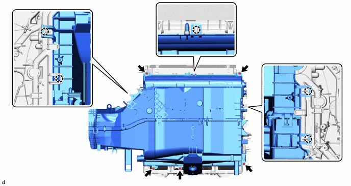
INSTALL HEATER COVER
-
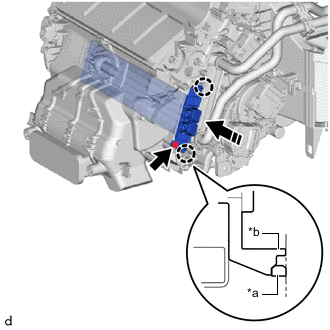
*a Heater Case Fitting Surface *b heater Cover Claw 
Install in this Direction Engage the claws to install the heater cover as shown in the illustration.
Note
-
Firmly push in until a "click" sound is heard.
-
Check that the heights of the claw fitting surface on the heater case and the claw of the heater cover are aligned.
-
-
Install the screw.
Note
If the claws of the heater cover are damaged, install the heater cover with screw (90159-60431).
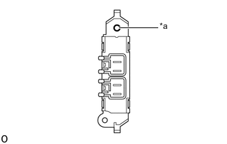
*a Screw Insertion Hole
-
-
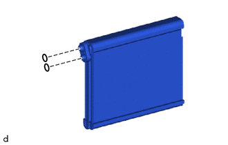
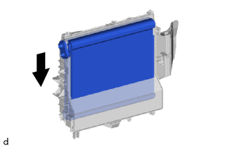
INSTALL HEATER RADIATOR UNIT SUB-ASSEMBLY
-
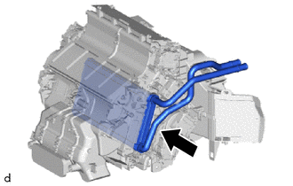
Install the heater radiator unit sub-assembly as shown in the illustration.
-
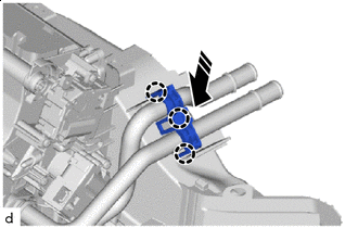
Install in this Direction Engage the claws to install the clamp as shown in the illustration.
-
-
INSTALL COOLER EXPANSION VALVE
-
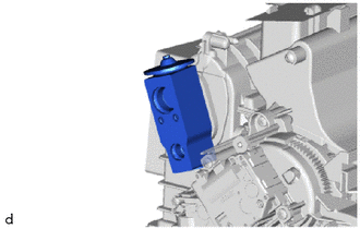
Install the cooler expansion valve.
-
-
INSTALL AIR CONDITIONER TUBE ASSEMBLY
-
Remove the vinyl tape from the air conditioner tube assembly.
-
Sufficiently apply compressor oil to 2 new O-rings and fitting surfaces of the air conditioner tube assembly.
Compressor Oil for HFC-134a (R134a) ND-OIL 8 or equivalent for HFO-1234yf (R1234yf) ND-OIL 12 or equivalent -
Install the 2 O-rings to the air conditioner tube assembly.
Note
Keep the O-rings and O-ring fitting surfaces free of foreign matter.
-
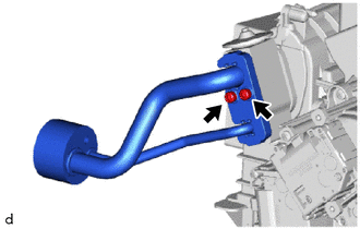
Using a 4 mm hexagon wrench, install the air conditioner tube assembly with the 2 hexagon bolts.
- Torque:
- 3.5 N*m { 36 kgf*cm, 31 in.*lbf }
-
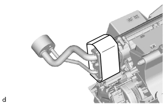
Install the butyl tape.
-
Remove any remaining No. 2 cooling unit packing from the air conditioner tube assembly.
-
Remove the release paper from a new No. 2 cooling unit packing.
-
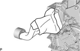
Install the No. 2 cooling unit packing.
-
-
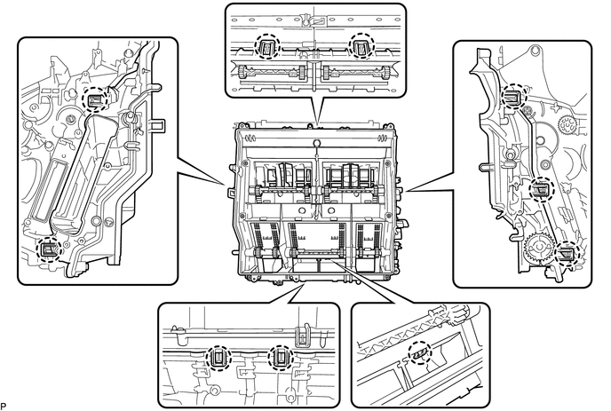
INSTALL AIR CONDITIONING HARNESS ASSEMBLY
-
except 3 zone type:
-
Engage the clamp.
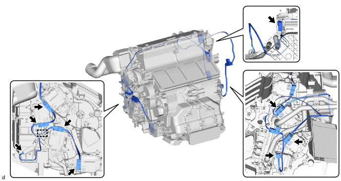
-
-
Connect 9 connectors to install the air conditioning harness assembly.
-
for 3 Zone Type:
-
Engage the clamp.
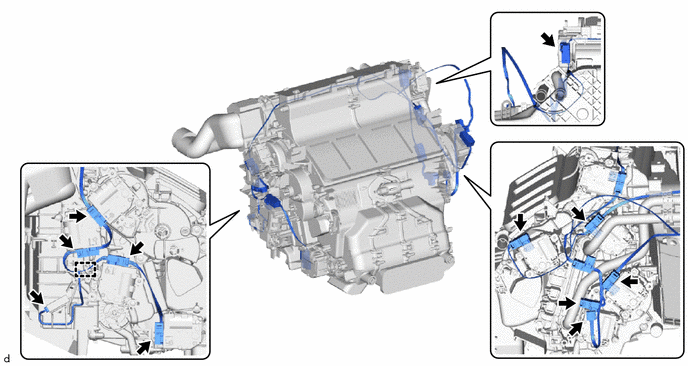
-
-
Connect 11 connectors to install the air conditioning harness assembly.
-
-
INSTALL ASPIRATOR PIPE
-
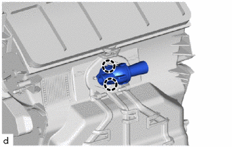
Engage the claws to install the aspirator pipe.
-
-
INSTALL BLOWER ASSEMBLY