AIR CONDITIONING UNIT INSTALLATION
PROCEDURE
-
INSTALL AIR CONDITIONING UNIT
-
Temporarily install the air conditioning unit to the instrument panel reinforcement assembly with the 3 bolts and 2 screws.
-
-
INSTALL INSTRUMENT PANEL REINFORCEMENT ASSEMBLY WITH AIR CONDITIONING UNIT
Note
Be sure to support the air conditioning unit assembly when installing it because failure to do so may cause the bracket of the air conditioning unit assembly to break.
-
Connect the ID code box (immobiliser code ECU) connector.
-
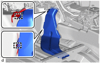
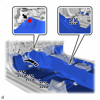
Engage the guides to temporarily install the instrument panel reinforcement assembly with air conditioning unit as shown in the illustration.
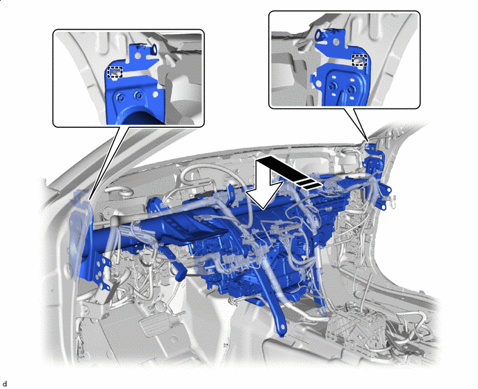

Install in this Direction - - -
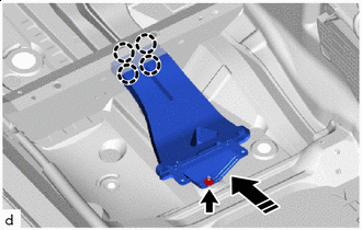
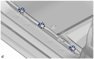
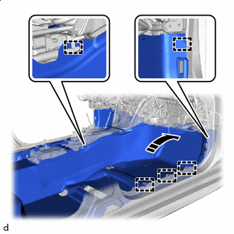
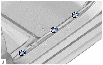
Using a 12 mm hexagon wrench, tighten the 3 collars as shown in the illustration.
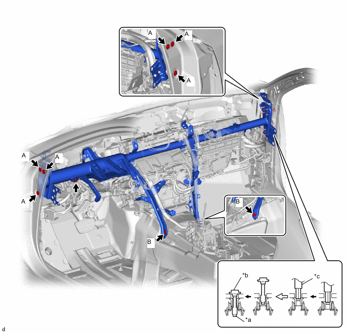
*a Collar *b Vehicle Body *c 12 mm Hexagon Wrench - - -
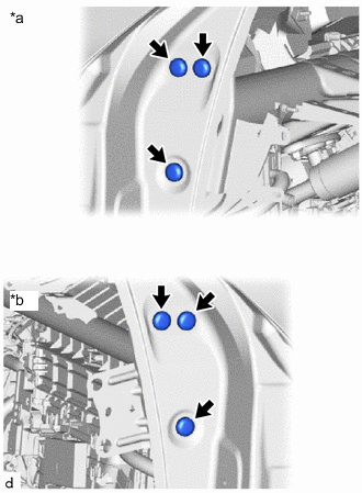
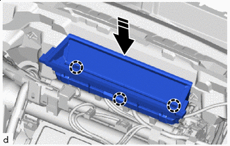
Install the 9 bolts.
- Torque:
- Bolt A
- 20 N*m { 204 kgf*cm, 15 ft.*lbf }
- Bolt B
- 21 N*m { 214 kgf*cm, 15 ft.*lbf }
-
Install the nut.
- Torque:
- 9.8 N*m { 100 kgf*cm, 87 in.*lbf }
-
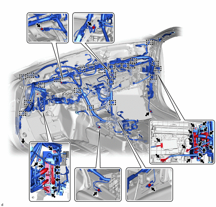
Install the 4 nuts and 2 bolts to connect the instrument panel wire.
-
Engage the clamps.
-
Connect the 15 connectors.
-
Install the 4 bolts to connect the 4 ground wires.
- Torque:
- 8.4 N*m { 86 kgf*cm, 74 in.*lbf }
-
-
FULLY TIGHTEN AIR CONDITIONING UNIT
-
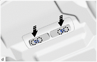
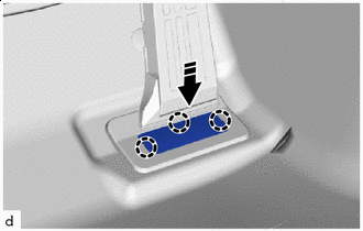
Tighten the 3 bolts and 2 screws in the order shown in the illustration.
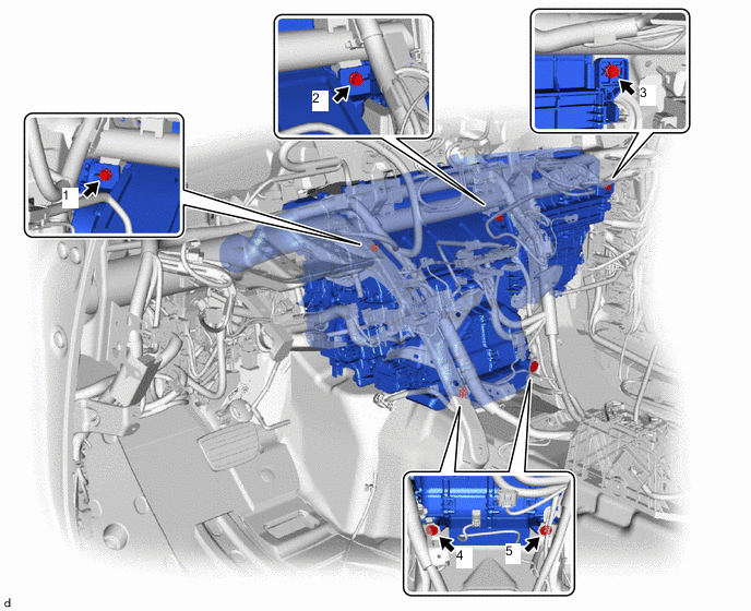
- Torque:
- 9.8 N*m { 100 kgf*cm, 87 in.*lbf }
-
Install the 2 bolts.
- Torque:
- 10 N*m { 102 kgf*cm, 7 ft.*lbf }
-
Install the 2 grommets.
-
-
INSTALL INSTRUMENT PANEL SAFETY PAD CAP
-
*a LH Side *b RH Side Install 6 new instrument panel safety pad caps.
-
-
INSTALL AIR HOSE
-
Install the air hose.
-
-
INSTALL LOWER DEFROSTER NOZZLE ASSEMBLY
Install in this Direction
-
Engage the claws to install the lower defroster nozzle assembly as shown in the illustration.
-
-
INSTALL NO. 1 AIR DUCT SUB-ASSEMBLY
-
Install the No. 1 air duct sub-assembly with the clip.
-
-
INSTALL NO. 1 CONSOLE BOX DUCT
-
Install the No. 1 console box duct with the 2 clips.
-
-
INSTALL REAR NO. 1 AIR DUCT
-
Install the rear No. 1 air duct.
-
Engage the clamps to connect the wire harness.
-
-
INSTALL REAR NO. 2 AIR DUCT
-
Install in this Direction Engage the claws to install the rear No. 2 air duct as shown in the illustration.
-
Install the nut.
-
Install the front floor silencer pad LH and center floor silencer pad LH.
-
Install in this Direction Install the front floor carpet assembly to the original position as shown in the illustration.
-
Engage the clamps.
-
Install the clip.
-
Engage the claws.
-
-
INSTALL REAR NO. 3 AIR DUCT
-
Install the rear No. 3 air duct.
-
Engage the clamps to connect the wire harness.
-
-
INSTALL REAR NO. 4 AIR DUCT
-
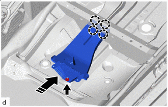
Install in this Direction Engage the claws to install the rear No. 4 air duct as shown in the illustration.
-
Install the nut.
-
Install the front floor silencer pad RH and center floor silencer pad RH.
-
Install in this Direction Install the front floor carpet assembly to the original position as shown in the illustration.
-
Engage the clamps.
-
Engage the claws.
-
-
INSTALL REAR NO. 5 AIR DUCT
-
Install the rear No. 5 air duct with the 2 screws.
Tech Tips
Use the same procedure for both sides.
-
-
INSTALL AIR DUCT PLUG
-
Install in this Direction Engage the claws to install the air duct plug as shown in the illustration.
Tech Tips
Use the same procedure for both air duct plugs.
-
-
INSTALL ACCELERATOR PEDAL
-
Install the accelerator peda with the 2 bolts.
- Torque:
- 5.4 N*m { 55 kgf*cm, 48 in.*lbf }
-
-
INSTALL ACCELERATOR PEDAL PAD
-
Install in this Direction Engage the claws to install the accelerator pedal pad.
-
-
INSTALL COOLER THERMISTOR
-
INSTALL AIR CONDITIONING AMPLIFIER ASSEMBLY
-
INSTALL ROLL RATE AND VERTICAL ACCELERATION SENSOR (YAWRATE SENSOR)
-
INSTALL NO. 2 AIR DUCT SUB-ASSEMBLY
-
Install the No. 2 air duct sub-assembly with the screw.
-
-
INSTALL STEERING COLUMN ASSEMBLY
-
INSTALL INSTRUMENT PANEL SAFETY PAD SUB-ASSEMBLY
-
INSTALL FRONT SEAT ASSEMBLY LH
-
INSTALL FRONT SEAT ASSEMBLY RH
Tech Tips
Use the same procedure as for the LH side.
-
CONNECT INLET HEATER WATER HOSE
-
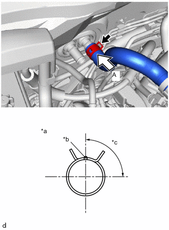
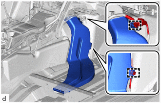
*a View A *b Marking (Green) *c Clip Installation Angle (75 to 105°) Connect the inlet heater water hose with the marking (green) facing up and engage the clip within the area shown in the illustration.
Note
Do not apply excessive force to the inlet heater water hose.
-
-
CONNECT OUTLET HEATER WATER HOSE
-
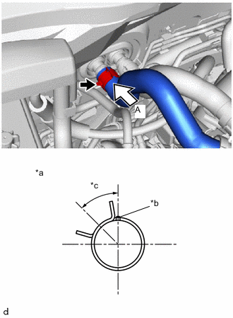
*a View A *b Marking (Green) *c Clip Installation Angle (30 to 60°) Connect the outlet heater water hose with the marking (green) facing up and engage the clip within the area shown in the illustration.
Note
Do not apply excessive force to the outlet heater water hose.
-
-
CONNECT COOLER REFRIGERANT LIQUID PIPE A
-
Remove the vinyl tape from the cooler refrigerant liquid pipe A.
-
Apply sufficient compressor oil to a new O-ring and fitting surface of the cooler refrigerant liquid pipe A.
Compressor Oil for HFC-134a (R134a) ND-OIL 8 or equivalent for HFO-1234yf (R1234yf) ND-OIL 12 or equivalent -
Install the O-ring to the cooler refrigerant liquid pipe A.
Note
Keep the O-rings and O-ring fitting surfaces free of foreign matter.
-
Connect the cooler refrigerant liquid pipe A.
-
-
CONNECT SUCTION PIPE SUB-ASSEMBLY
-
Remove the vinyl tape from the suction pipe sub-assembly.
-
Apply sufficient compressor oil to a new O-ring and fitting surface of the suction pipe sub-assembly.
Compressor Oil for HFC-134a (R134a) ND-OIL 8 or equivalent for HFO-1234yf (R1234yf) ND-OIL 12 or equivalent -
Install the O-ring to the suction pipe sub-assembly.
Note
Keep the O-rings and O-ring fitting surfaces free of foreign matter.
-
Connect the suction pipe sub-assembly.
-
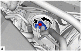
Install in this Direction Rotate the hook connector as shown in the illustration.
-
Insert the pipe joint into the fitting hole securely and install the bolt.
- Torque:
- 9.8 N*m { 100 kgf*cm, 87 in.*lbf }
-
-
INSTALL WINDSHIELD WIPER MOTOR AND LINK ASSEMBLY
-
ADD ENGINE COOLANT
-
INSPECT FOR ENGINE COOLANT
-
INSTALL NO. 1 ENGINE UNDER COVER ASSEMBLY
-
INSTALL NO. 1 INLET AIR CLEANER
-
INSTALL AIR CLEANER CAP WITH AIR CLEANER HOSE
-
CHARGE AIR CONDITIONING SYSTEM WITH REFRIGERANT
-
WARM UP ENGINE
-
INSPECT FOR REFRIGERANT LEAK
-
INSTALL V-BANK COVER SUB-ASSEMBLY
-
INITIALIZE SERVO MOTOR
-
INSTALL COOL AIR INTAKE DUCT SEAL