FRONT POWER SEAT CONTROL SYSTEM Power Seat does not Return to Memorized Position
DESCRIPTION
Tech Tips
-
The position control ECU and switch assembly is a collective term for the position control ECU and switch assembly (driver seat) and the position control ECU and switch assembly (front passenger seat).
-
The seat memory switch is a collective term for the seat memory switch (driver door) and the seat memory switch (front passenger door).
-
The front multiplex network door ECU is a collective term for the front multiplex network door ECU (driver door) and the front multiplex network door ECU (front passenger door).
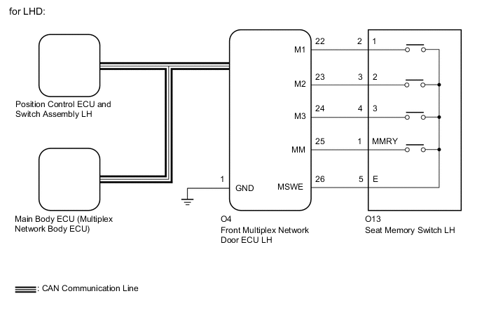
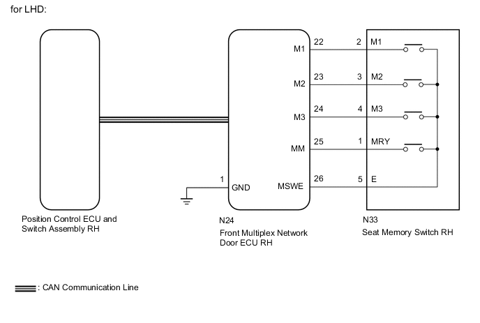
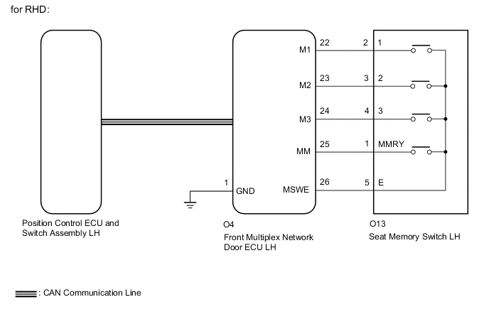
When either the M1, M2 or M3 switch is pressed, the front multiplex network door ECU sends a switch signal to the main body ECU (multiplex network body ECU) via CAN communication. Then, the main body ECU (multiplex network body ECU) sends a recall request signal to the position control ECU and switch assembly. The position control ECU and switch assembly operates each motor to achieve each memorized position value.
WIRING DIAGRAM
-
for Driver Seat

-
for Front Passenger Seat
CAUTION / NOTICE / HINT
Note
-
The seat position will not be stored if the SET switch and 2 or more of the seat memory switches (for example, M1 switch and M2 switch) are pressed simultaneously.
If a memorizing operation has failed, release all switches. The seat memory function does not operate unless the switches are released.
-
The seat will not return to the memorized position if 2 or more of the seat memory switches (for example, M1 switch and M2 switch) are pressed simultaneously.
If a restoring operation has failed, release all switches. The seat memory restoring function does not operate unless the switches are released.
-
The front power seat control system uses the CAN communication system. First, confirm that there are no malfunctions in the CAN communication system. Refer to How to Proceed with Troubleshooting.
-
Before replacing the main body ECU (multiplex network body ECU), refer to Service Bulletin.
PROCEDURE
-
CHECK FRONT POWER SEAT CONTROL OPERATION
-
Check that each function of the power seat operates normally by using the switches on the position control ECU and switch assembly.
OK Each function of the power seat operates normally using the switches on the position control ECU and switch assembly. Result Proceed to OK NG
NG 
GO TO PROBLEM SYMPTOMS TABLE Click here
OK 
-
-
CHECK SEAT POSITION MEMORY FUNCTION
-
Check that the seat position memory function.
Note
-
The seat position will not be stored if the SET switch and 2 or more of the seat memory switches (for example, M1 switch and M2 switch) are pressed simultaneously.
-
If a memorizing operation has failed, release all switches. The seat memory function does not operate unless the switches are released.
OK Seat position memory function is normal. Result Result Proceed to OK (Driver Seat) A OK (Front Passenger Seat) B NG C -
B 
CHECK SEAT POSITION RESTORING FUNCTION Click here
C
GO TO OTHER DIAGNOSTIC PROCEDURE (Power Seat Position is not Memorized) Click here
A
-
-
CHECK SEAT POSITION RESTORING FUNCTION
-
Under each of the following conditions, check that the seat position restoring function operates by pressing the M1, M2 or M3 switch.
-
The engine switch is on (IG), and the shift lever is in P.*1
-
The engine switch is turned off within 180 seconds after the driver door is closed and opened.*2
-
The engine switch is turned off within 60 seconds after the driver door is opened and closed.*3
Result Result Proceed to Seat position restoring function does not operate at all. A Seat position restoring function does not operate when the condition is *1. B
-
Seat position restoring function does not operate when the condition is *2.
-
Seat position restoring function does not operate when the condition is *3.
C -
B
READ VALUE USING GTS (SHIFT SW POSITION) Click here
C
READ VALUE USING GTS (DOOR COURTESY SW) Click here
A
-
-
READ VALUE USING GTS (SEAT MEMORY)
-
Store a seat position in memory for each of the M1, M2 and M3 switches.
-
Connect the GTS to the DLC3.
-
Turn the engine switch on (IG).
-
Turn the GTS on.
-
Enter the following menus: Body Electrical / Driver Seat / Data List.
-
Read the Data List according to the display on the GTS.
Body Electrical > Driver Seat > Data ListTester Display Measurement Item Range Normal Condition Diagnostic Note Seat Memory No1 Seat position memorized with M1 switch Mem or Not Mem Mem: Memorized
Not Mem: Not memorized
- Seat Memory No2 Seat position memorized with M2 switch Mem or Not Mem Mem: Memorized
Not Mem: Not memorized
- Seat Memory No3 Seat position memorized with M13 switch Mem or Not Mem Mem: Memorized
Not Mem: Not memorized
-
Body Electrical > Driver Seat > Data ListTester Display Seat Memory No1 Seat Memory No2 Seat Memory No3 OK Mem appears on the GTS screen. Result Proceed to OK NG
NG
GO TO OTHER DIAGNOSTIC PROCEDURE (Power Seat Position is not Memorized) Click here
OK
-
-
REPLACE FRONT MULTIPLEX NETWORK DOOR ECU (DRIVER DOOR)
-
Temporarily replace the front multiplex network door ECU (driver door) with a new or known good one.
Result Proceed to NEXT
NEXT
-
-
CHECK SEAT POSITION MEMORY AND RESTORING FUNCTION
-
Check that the seat position memory and restoring function.
Note
-
The seat position will not be stored if the SET switch and 2 or more of the seat memory switches (for example, M1 switch and M2 switch) are pressed simultaneously.
-
If a memorizing operation has failed, release all switches. The seat memory function does not operate unless the switches are released.
OK Seat position memory and restoring function operates normally. Result Proceed to OK NG -
OK
END (FRONT MULTIPLEX NETWORK DOOR ECU (DRIVER DOOR) WAS DEFECTIVE)
NG
-
-
REPLACE POSITION CONTROL ECU AND SWITCH ASSEMBLY (DRIVER SEAT)
-
Temporarily replace the position control ECU and switch assembly (driver seat) with a new or known good one.
Result Proceed to NEXT
NEXT
-
-
CHECK SEAT POSITION MEMORY AND RESTORING FUNCTION
-
Check that the seat position memory and restoring function.
Note
-
The seat position will not be stored if the SET switch and 2 or more of the seat memory switches (for example, M1 switch and M2 switch) are pressed simultaneously.
-
If a memorizing operation has failed, release all switches. The seat memory function does not operate unless the switches are released.
OK Seat position memory and restoring function operates normally. Result Proceed to OK NG -
OK
END (POSITION CONTROL ECU AND SWITCH ASSEMBLY (DRIVER SEAT) WAS DEFECTIVE)
NG
REPLACE MAIN BODY ECU (MULTIPLEX NETWORK BODY ECU) Click here
-
-
READ VALUE USING GTS (SHIFT SW POSITION)
-
Connect the GTS to the DLC3.
-
Turn the engine switch on (IG).
-
Turn the GTS on.
-
Enter the following menus: Body Electrical / Driver Seat / Data List.
-
Read the Data List according to the display on the GTS.
Body Electrical > Driver Seat > Data ListTester Display Measurement Item Range Normal Condition Diagnostic Note Shift SW Position Park state signal Shift P or Shift Other Shift P: Shift lever in P
Shift Other: Shift lever in a position other than P
-
Body Electrical > Driver Seat > Data ListTester Display Shift SW Position OK On the GTS screen, the item changes between ON and OFF according to the above. Result Proceed to OK NG
OK
REPLACE POSITION CONTROL ECU AND SWITCH ASSEMBLY (DRIVER SEAT) Click here
NG
GO TO AUTOMATIC TRANSAXLE SYSTEM (P0705) Click here
-
-
READ VALUE USING GTS (DOOR COURTESY SW)
-
Connect the GTS to the DLC3.
-
Turn the engine switch on (IG).
-
Turn the GTS on.
-
Enter the following menus: Body Electrical / Main Body / Data List.
-
Read the Data List according to the display on the GTS.
Body Electrical > Main Body > Data ListTester Display Measurement Item Range Normal Condition Diagnostic Note FR Door Courtesy SW Front door courtesy light switch assembly (driver door) signal*2 ON or OFF ON: Driver door open
OFF: Driver door closed
- FL Door Courtesy SW Front door courtesy light switch assembly (driver door) signal*1 ON or OFF ON: Driver door open
OFF: Driver door closed
-
-
*1: for LHD
-
*2: for RHD
Body Electrical > Main Body > Data ListTester Display FR Door Courtesy SW FL Door Courtesy SW OK On the GTS screen, the item changes between ON and OFF according to the above. Result Proceed to OK NG -
OK
REPLACE POSITION CONTROL ECU AND SWITCH ASSEMBLY (DRIVER SEAT) Click here
NG
GO TO LIGHTING SYSTEM (Door Courtesy Switch Circuit) Click here
-
-
CHECK SEAT POSITION RESTORING FUNCTION
-
Under each of the following conditions, check that the seat position restoring function operates by pressing the M1, M2 or M3 switch.
-
The engine switch is on (IG), and the shift lever is in P.*1
-
The engine switch is turned off within 180 seconds after the front passenger door is closed and opened.*2
Result Result Proceed to Seat position restoring function does not operate at all. A Seat position restoring function does not operate when the condition is *1. B Seat position restoring function does not operate when the condition is *2. C -
B
READ VALUE USING GTS (SHIFT SW POSITION) Click here
C
READ VALUE USING GTS (DOOR COURTESY SW) Click here
A
-
-
READ VALUE USING GTS (SEAT MEMORY)
-
Store a seat position in memory for each of the M1, M2 and M3 switches.
-
Connect the GTS to the DLC3.
-
Turn the engine switch on (IG).
-
Turn the GTS on.
-
Enter the following menus: Body Electrical / Passenger Seat / Data List.
-
Read the Data List according to the display on the GTS.
Body Electrical > Passenger Seat > Data ListTester Display Measurement Item Range Normal Condition Diagnostic Note Seat Memory No1 Seat position memorized with M1 switch Mem or Not Mem Mem: Memorized
Not Mem: Not memorized
- Seat Memory No2 Seat position memorized with M2 switch Mem or Not Mem Mem: Memorized
Not Mem: Not memorized
- Seat Memory No3 Seat position memorized with M3 switch Mem or Not Mem Mem: Memorized
Not Mem: Not memorized
-
Body Electrical > Passenger Seat > Data ListTester Display Seat Memory No1 Seat Memory No2 Seat Memory No3 OK Mem appears on the GTS screen. Result Proceed to OK NG
NG
GO TO OTHER DIAGNOSTIC PROCEDURE (Power Seat Position is not Memorized) Click here
OK
-
-
REPLACE FRONT MULTIPLEX NETWORK DOOR ECU (FRONT PASSENGER DOOR)
-
Temporarily replace the front multiplex network door ECU (front passenger door) with a new or known good one.
Result Proceed to NEXT
NEXT
-
-
CHECK SEAT POSITION MEMORY AND RESTORING FUNCTION
-
Check that the seat position memory and restoring function.
Note
-
The seat position will not be stored if the SET switch and 2 or more of the seat memory switches (for example, M1 switch and M2 switch) are pressed simultaneously.
-
If a memorizing operation has failed, release all switches. The seat memory function does not operate unless the switches are released.
OK Seat position memory and restoring function operates normally. Result Proceed to OK NG -
OK
END (FRONT MULTIPLEX NETWORK DOOR ECU (FRONT PASSENGER DOOR) WAS DEFECTIVE)
NG
REPLACE POSITION CONTROL ECU AND SWITCH ASSEMBLY (FRONT PASSENGER SEAT)
-
-
READ VALUE USING GTS (SHIFT SW POSITION)
-
Connect the GTS to the DLC3.
-
Turn the engine switch on (IG).
-
Turn the GTS on.
-
Enter the following menus: Body Electrical / Passenger Seat / Data List.
-
Read the Data List according to the display on the GTS.
Body Electrical > Passenger Seat > Data ListTester Display Measurement Item Range Normal Condition Diagnostic Note Shift SW Position Park state signal Shift P or Shift Other Shift P: Shift lever in P
Shift Other: Shift lever in a position other than P
-
Body Electrical > Passenger Seat > Data ListTester Display Shift SW Position OK On the GTS screen, the item changes between ON and OFF according to the above. Result Proceed to OK NG
OK
REPLACE POSITION CONTROL ECU AND SWITCH ASSEMBLY (FRONT PASSENGER SEAT) Click here
NG
GO TO AUTOMATIC TRANSAXLE SYSTEM (P0705) Click here
-
-
READ VALUE USING GTS (DOOR COURTESY SW)
-
Connect the GTS to the DLC3.
-
Turn the engine switch on (IG).
-
Turn the GTS on.
-
Enter the following menus: Body Electrical / Main Body / Data List.
-
Read the Data List according to the display on the GTS.
Body Electrical > Main Body > Data ListTester Display Measurement Item Range Normal Condition Diagnostic Note FR Door Courtesy SW Front door courtesy light switch assembly (front passenger door) signal*1 ON or OFF ON: Front passenger door open
OFF: Front passenger door closed
- FL Door Courtesy SW Front door courtesy light switch assembly (front passenger door) signal*2 ON or OFF ON: Front passenger door open
OFF: Front passenger door closed
-
-
*1: for LHD
-
*2: for RHD
Body Electrical > Main Body > Data ListTester Display FR Door Courtesy SW FL Door Courtesy SW OK On the GTS screen, the item changes between ON and OFF according to the above. Result Proceed to OK NG -
OK
REPLACE POSITION CONTROL ECU AND SWITCH ASSEMBLY (FRONT PASSENGER SEAT) Click here
NG
GO TO LIGHTING SYSTEM (Door Courtesy Switch Circuit) Click here
-