FRONT POWER SEAT CONTROL SYSTEM Front Power Seat does not Operate with Front Power Seat Switch
DESCRIPTION
Tech Tips
The position control ECU and switch assembly is a collective term for the position control ECU and switch assembly (driver seat) and the position control ECU and switch assembly (front passenger seat).
Signals are input into the position control ECU and switch assembly. The built-in ECU manages the signals received from the power seat switch, and operates each motor. If the position control ECU and switch assembly receives more than 2 motor operation signals for the same motor, the motor will be stopped. Manual operation is restarted when the position control ECU and switch assembly receives 1 signal only.
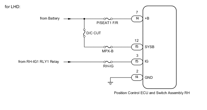
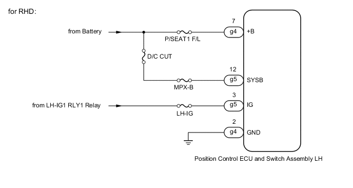
WIRING DIAGRAM
-
for Driver Seat


-
for Front Passenger Seat
CAUTION / NOTICE / HINT
Note
Inspect the fuses for circuits related to this system before performing the following procedure.
PROCEDURE
-
CHECK FRONT POWER SEAT OPERATION
-
Check that each function of the power seat operates normally by using the position control ECU and switch assembly.
Result Result Proceed to All power seat functions do not operate (Driver Seat) A All power seat functions do not operate (Front Passenger Seat) B One or more power seat functions do not operate C
B 
CHECK HARNESS AND CONNECTOR (POSITION CONTROL ECU AND SWITCH ASSEMBLY (FRONT PASSENGER SEAT) - POWER SUPPLY) Click here
C 
GO TO OTHER DIAGNOSTIC PROCEDURE (One or more Power Seat Motors do not Operate) Click here
A 
-
-
CHECK HARNESS AND CONNECTOR (POSITION CONTROL ECU AND SWITCH ASSEMBLY (DRIVER SEAT) - POWER SUPPLY)
-
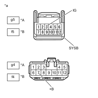
*A for LHD *B for RHD *a Front view of wire harness connector
(to Position Control ECU and Switch Assembly (Driver Seat))
Disconnect the position control ECU and switch assembly (driver seat) connectors.
-
Measure the voltage according to the value(s) in the table below.
Standard Voltage for LHD Tester Connection Condition Specified Condition g4-7 (+B) - Body ground Always 11 to 14 V g5-12 (SYSB) - Body ground Always 11 to 14 V g5-3 (IG) - Body ground Engine switch on (IG) 11 to 14 V g5-3 (IG) - Body ground Engine switch off Below 1 V for RHD Tester Connection Condition Specified Condition f4-7 (+B) - Body ground Always 11 to 14 V f5-12 (SYSB) - Body ground Always 11 to 14 V f5-3 (IG) - Body ground Engine switch on (IG) 11 to 14 V f5-3 (IG) - Body ground Engine switch off Below 1 V Result Proceed to OK NG
NG
REPAIR OR REPLACE HARNESS OR CONNECTOR
OK
-
-
CHECK HARNESS AND CONNECTOR (POSITION CONTROL ECU AND SWITCH ASSEMBLY (DRIVER SEAT) - BODY GROUND)
-
Measure the resistance according to the value(s) in the table below.
Standard Resistance for LHD Tester Connection Condition Specified Condition g4-2 (GND) - Body ground Always Below 1 Ω for RHD Tester Connection Condition Specified Condition f4-2 (GND) - Body ground Always Below 1 Ω Result Proceed to OK NG
OK
REPLACE POSITION CONTROL ECU AND SWITCH ASSEMBLY (DRIVER SEAT) Click here
NG
REPAIR OR REPLACE HARNESS OR CONNECTOR
-
-
CHECK HARNESS AND CONNECTOR (POSITION CONTROL ECU AND SWITCH ASSEMBLY (FRONT PASSENGER SEAT) - POWER SUPPLY)
-
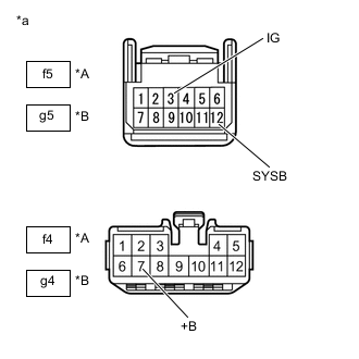
*A for LHD *B for RHD *a Front view of wire harness connector
(to Position Control ECU and Switch Assembly (Front Passenger Seat))
Disconnect the position control ECU and switch assembly (front passenger seat) connectors.
-
Measure the voltage according to the value(s) in the table below.
Standard Voltage for LHD Tester Connection Condition Specified Condition f4-7 (+B) - Body ground Always 11 to 14 V f5-12 (SYSB) - Body ground Always 11 to 14 V f5-3 (IG) - Body ground Engine switch on (IG) 11 to 14 V f5-3 (IG) - Body ground Engine switch off Below 1 V for RHD Tester Connection Condition Specified Condition g4-7 (+B) - Body ground Always 11 to 14 V g5-12 (SYSB) - Body ground Always 11 to 14 V g5-3 (IG) - Body ground Engine switch on (IG) 11 to 14 V g5-3 (IG) - Body ground Engine switch off Below 1 V Result Proceed to OK NG
NG
REPAIR OR REPLACE HARNESS OR CONNECTOR
OK
-
-
CHECK HARNESS AND CONNECTOR (POSITION CONTROL ECU AND SWITCH ASSEMBLY (FRONT PASSENGER SEAT) - BODY GROUND)
-
Measure the resistance according to the value(s) in the table below.
Standard Resistance for LHD Tester Connection Condition Specified Condition f4-2 (GND) - Body ground Always Below 1 Ω for RHD Tester Connection Condition Specified Condition g4-2 (GND) - Body ground Always Below 1 Ω Result Proceed to OK NG
OK
REPLACE POSITION CONTROL ECU AND SWITCH ASSEMBLY (FRONT PASSENGER SEAT) Click here
NG
REPAIR OR REPLACE HARNESS OR CONNECTOR
-