PRE-CRASH SAFETY SYSTEM, Diagnostic DTC:U1002
| DTC Code | DTC Name |
|---|---|
| U1002 | Lost Communication with Gateway Module |
DESCRIPTION
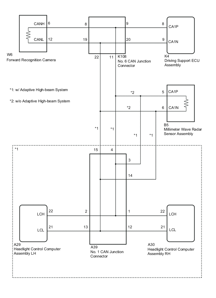
This DTC is stored when the driving support ECU assembly cannot receive signals from the forward recognition camera or millimeter wave radar sensor assembly.
| DTC No. | Detection Item | DTC Detection Condition | Trouble Area |
|---|---|---|---|
| U1002 | Lost Communication with Gateway Module | After the engine switch is turned on, communication between the driving support ECU and any of the following components is abnormal for 2 seconds or more
|
|
WIRING DIAGRAM
CAUTION / NOTICE / HINT
Note
-
Before measuring the resistance of the CAN bus, turn the engine switch off and leave the vehicle for 1 minute or more without operating the key or any switches, or opening or closing the doors. After that, disconnect the cable from the negative (-) battery terminal and leave the vehicle for 1 minute or more before measuring the resistance.
-
After turning the engine switch off, waiting time may be required before disconnecting the cable from the negative (-) battery terminal. Therefore, make sure to read the disconnecting the cable from the negative (-) battery terminal notices before proceeding with work.
-
When replacing the millimeter wave radar sensor assembly, always replace it with a new one. If a millimeter wave radar sensor assembly which was installed to another vehicle is used, the information stored in the millimeter wave radar sensor assembly will not match the information from the vehicle. As a result, a DTC may be stored.
-
When the millimeter wave radar sensor assembly is replaced with a new one, adjustment of the radar sensor beam axis must be performed.
-
When replacing the forward recognition camera, always replace it with a new one. If a forward recognition camera which was installed to another vehicle is used, the information stored in the forward recognition camera will not match the information from the vehicle. As a result, a DTC may be stored.
-
If the forward recognition camera has been replaced with a new one, be sure to perform Forward Recognition Camera Learning.
Tech Tips
-
Operating the engine switch, any other switches or a door triggers related ECU and sensor communication on the CAN. This communication will cause the resistance value to change.
-
Even after DTCs are cleared, if a DTC is stored again after driving the vehicle for a while, the malfunction may be occurring due to vibration of the vehicle. In such a case, wiggling the ECUs or wire harness while performing the inspection below may help determine the cause of the malfunction.
PROCEDURE
-
CONFIRM VEHICLE TYPE
-
Confirm vehicle type.
Result Result Proceed to w/o Adaptive High-beam System A w/ Adaptive High-beam System B
B 
CHECK CAN BUS LINE (MALFUNCTION CONFIRMATION) Click here
A 
-
-
CHECK CAN BUS LINE (MALFUNCTION CONFIRMATION)
-
Turn the engine switch off.
-
Disconnect the cable from the negative (-) battery terminal.
-
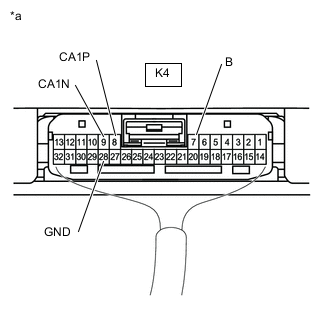
*a Component with harness connected
(Driving Support ECU Assembly)
Measure the resistance according to the value(s) in the table below.
Standard Resistance Tester Connection Condition Specified Condition Result K4-8 (CA1P) - K4-9 (CA1N) Cable disconnected from negative (-) battery terminal 54 to 69 Ω Below 54 Ω:
Short circuit between bus lines
70 Ω or more:
Open circuit in a main bus line or driving support ECU assembly branch line
K4-8 (CA1P) - K4-28 (GND) Cable disconnected from negative (-) battery terminal 200 Ω or higher Below 200 Ω:
CANH ground short
K4-9 (CA1N) - K4-28 (GND) Cable disconnected from negative (-) battery terminal 200 Ω or higher Below 200 Ω:
CANH ground short
K4-8 (CA1P) - K4-7 (B) Cable disconnected from negative (-) battery terminal 6 kΩ or higher Below 6 kΩ:
CANH +B short
K4-9 (CA1N) - K4-7 (B) Cable disconnected from negative (-) battery terminal 6 kΩ or higher Below 6 kΩ:
CANH +B short
Result Result Proceed to OK A NG (Open circuit in main line or Driving support ECU assembly branch line) B NG (Short circuit between main lines) C NG (Short to +B or ground) D
B
CHECK FOR OPEN IN CAN BUS BRANCH LINES (DRIVING SUPPORT ECU ASSEMBLY) Click here
C
CHECK FOR SHORT BETWEEN CAN BUS LINES (FORWARD RECOGNITION CAMERA) Click here
D
CHECK FOR SHORT IN CAN BUS LINE (FORWARD RECOGNITION CAMERA) Click here
A
-
-
CHECK FOR DTCs (PRE-CRASH SAFETY SYSTEM)
-
Clear the DTCs.
Body Electrical > Pre-Crash 2 > Clear DTCs -
Perform the following procedure.
Tech Tips
If the following procedure is not performed, the previously output DTC cannot be detected.
-
Turn the engine switch on (IG) and wait 2 seconds or more.
-
-
Check for DTCs.
Body Electrical > Pre-Crash 2 > Trouble CodesResult Result Proceed to DTC U1002 is not output A DTC U1002 is output B
A 
USE SIMULATION METHOD TO CHECK Click here
B
REPLACE DRIVING SUPPORT ECU ASSEMBLY Click here
-
-
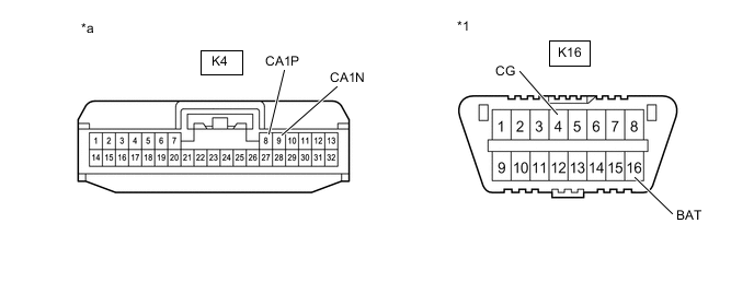
CHECK FOR OPEN IN CAN BUS BRANCH LINES (DRIVING SUPPORT ECU ASSEMBLY)
-
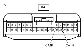
*a Front view of wire harness connector
(to Driving Support ECU Assembly)
Disconnect the driving support ECU assembly connector.
-
Measure the resistance according to the value(s) in the table below.
Standard Resistance Tester Connection Condition Specified Condition K4-8 (CA1P) - K4-9 (CA1N) Cable disconnected from negative (-) battery terminal 108 to 132 Ω Tech Tips
If the resistance is between 108 and 132 Ω, there may be an open in a CAN bus main line. If the value is 132 Ω or more, there may be an open in a CAN bus branch line between the No. 6 CAN junction connector and the driving support ECU or a connector may be disconnected.
-
Connect the K4 driving support ECU assembly connector.
Result Proceed to OK NG
NG
CHECK FOR OPEN IN CAN BUS BRANCH LINES (DRIVING SUPPORT ECU ASSEMBLY) Click here
OK
-
-
CHECK FOR OPEN IN CAN BUS MAIN LINES (NO. 6 CAN JUNCTION CONNECTOR)
-
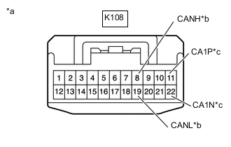
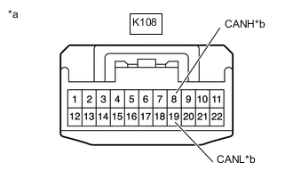
*a Front view of wire harness connector
(to No. 6 CAN Junction Connector)
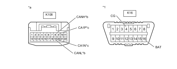
*b to Forward Recognition Camera *c to Millimeter Wave Radar Sensor Assembly Disconnect the No. 6 CAN junction connector.
-
Measure the resistance according to the value(s) in the table below.
Standard Resistance Tester Connection Condition Specified Condition Connected to K108-19 (CANL) - K108-8 (CANH) Cable disconnected from negative (-) battery terminal 108 to 132 Ω Forward Recognition Camera K108-11 (CA1P) - K108-22 (CA1N) Cable disconnected from negative (-) battery terminal 108 to 132 Ω Millimeter Wave Radar Sensor Assembly -
Connect the K108 No. 6 CAN junction connector.
Result Result Proceed to OK A NG (Forward Recognition Camera Main Line) B NG (Millimeter Wave Radar Sensor Assembly) C
A
REPLACE NO. 6 CAN JUNCTION CONNECTOR
C
CHECK FOR OPEN IN CAN BUS MAIN LINES (MILLIMETER WAVE RADAR SENSOR ASSEMBLY) Click here
B
-
-
CHECK FOR OPEN IN CAN BUS MAIN LINES (FORWARD RECOGNITION CAMERA)
-
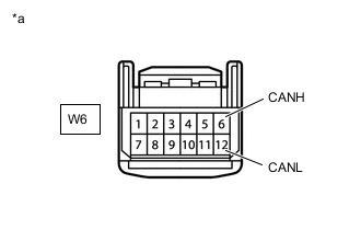
*a Front view of wire harness connector
(to Forward Recognition Camera)
Disconnect the forward recognition camera connector.
-
Measure the resistance according to the value(s) in the table below.
Standard Resistance Tester Connection Condition Specified Condition W6-6 (CANH) - W6-12 (CANL) Cable disconnected from negative (-) battery terminal 108 to 132 Ω -
Connect the W6 forward recognition camera connector.
Result Proceed to OK NG
OK
REPLACE FORWARD RECOGNITION CAMERA Click here
NG
REPAIR OR REPLACE CAN BUS MAIN LINE OR CONNECTOR (NO. 6 CAN JUNCTION CONNECTOR - FORWARD RECOGNITION CAMERA)
-
-
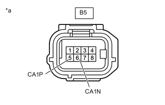
CHECK FOR OPEN IN CAN BUS MAIN LINES (MILLIMETER WAVE RADAR SENSOR ASSEMBLY)
-

*a Front view of wire harness connector
(to Millimeter Wave Radar Sensor Assembly)
Disconnect the millimeter wave radar sensor assembly connector.
-
Measure the resistance according to the value(s) in the table below.
Standard Resistance Tester Connection Condition Specified Condition B5-5 (CA1P) - B5-6 (CA1N) Cable disconnected from negative (-) battery terminal 108 to 132 Ω -
Connect the B5 millimeter wave radar sensor assembly connector.
Result Proceed to OK NG
OK
REPLACE MILLIMETER WAVE RADAR SENSOR ASSEMBLY Click here
NG
REPAIR OR REPLACE CAN BUS MAIN LINE OR CONNECTOR (NO. 6 CAN JUNCTION CONNECTOR - MILLIMETER WAVE RADAR SENSOR ASSEMBLY)
-
-
CHECK FOR OPEN IN CAN BUS BRANCH LINES (DRIVING SUPPORT ECU ASSEMBLY)
-

*a Front view of wire harness connector
(to Driving Support ECU Assembly)
Disconnect the driving support ECU assembly connector.
-
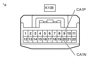
*a Front view of wire harness connector
(to No. 6 CAN Junction Connector)
Disconnect the No. 6 CAN junction connector.
-
Measure the resistance according to the value(s) in the table below.
Standard Resistance Tester Connection Condition Specified Condition K108-9 (CA1P) - K4-8 (CA1P) Cable disconnected from negative (-) battery terminal Below 1 Ω K108-20 (CA1N) - K4-9 (CA1N) Cable disconnected from negative (-) battery terminal Below 1 Ω -
Connect the K108 No. 6 CAN junction connector.
-
Connect the K4 driving support ECU assembly connector.
Result Proceed to OK NG
OK
REPLACE NO. 6 CAN JUNCTION CONNECTOR
NG
REPAIR OR REPLACE CAN BUS BRANCH WIRE (NO. 6 CAN JUNCTION CONNECTOR - DRIVING SUPPORT ECU ASSEMBLY)
-
-
CHECK FOR SHORT BETWEEN CAN BUS LINES (FORWARD RECOGNITION CAMERA)
-

*a Front view of wire harness connector
(to Forward Recognition Camera)
Disconnect the forward recognition camera connector.
-
Measure the resistance according to the value(s) in the table below.
Standard Resistance Tester Connection Condition Specified Condition W6-6 (CANH) - W6-12 (CANL) Cable disconnected from negative (-) battery terminal 108 to 132 Ω -
Connect the W6 forward recognition camera connector.
Result Proceed to OK NG
OK
REPLACE FORWARD RECOGNITION CAMERA Click here
NG
-
-
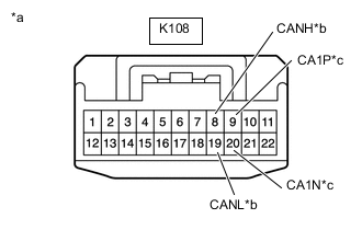
CHECK FOR SHORT BETWEEN CAN BUS LINES (NO. 6 CAN JUNCTION CONNECTOR)
-
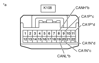
*a Front view of wire harness connector
(to No. 6 CAN junction connector)
*b to Forward Recognition Camera *c to Driving Support ECU Assembly *d to Millimeter Wave Radar Sensor Assembly Disconnect the No. 6 CAN junction connector.
-
Measure the resistance according to the value(s) in the table below.
Standard Resistance Tester Connection Condition Specified Condition Connected to K108-19 (CANL) - K108-8 (CANH) Cable disconnected from negative (-) battery terminal 108 to 132 Ω Forward Recognition Camera K108-11 (CA1P) - K108-22 (CA1N) Cable disconnected from negative (-) battery terminal 108 to 132 Ω Millimeter Wave Radar Sensor Assembly K108-9 (CA1P) - K108-20 (CA1N) Cable disconnected from negative (-) battery terminal 200 Ω or higher Driving Support ECU Assembly -
Connect the K108 No. 6 CAN junction connector.
Result Result Proceed to OK A NG (Forward Recognition Camera Main Line) B NG (Millimeter Wave Radar Sensor Assembly Main Line) C NG (Driving Support ECU Assembly Branch Line) D
A
REPLACE NO. 6 CAN JUNCTION CONNECTOR
B
REPAIR OR REPLACE CAN BUS MAIN LINE OR CONNECTOR (NO. 6 CAN JUNCTION CONNECTOR - FORWARD RECOGNITION CAMERA)
D
CHECK FOR SHORT BETWEEN CAN BUS LINES (DRIVING SUPPORT ECU ASSEMBLY) Click here
C
-
-
CHECK FOR SHORT BETWEEN CAN BUS LINES (MILLIMETER WAVE RADAR SENSOR ASSEMBLY)
-
*a Front view of wire harness connector
(to Millimeter Wave Radar Sensor Assembly)
Disconnect the millimeter wave radar sensor assembly connector.
-
Measure the resistance according to the value(s) in the table below.
Standard Resistance Tester Connection Condition Specified Condition B5-5 (CA1P) - B5-6 (CA1N) Cable disconnected from negative (-) battery terminal 108 to 132 Ω -
Connect the B5 millimeter wave radar sensor assembly connector.
Result Proceed to OK NG
OK
REPLACE MILLIMETER WAVE RADAR SENSOR ASSEMBLY Click here
NG
REPAIR OR REPLACE CAN BUS MAIN LINE OR CONNECTOR (NO. 6 CAN JUNCTION CONNECTOR - MILLIMETER WAVE RADAR SENSOR ASSEMBLY)
-
-
CHECK FOR SHORT BETWEEN CAN BUS LINES (DRIVING SUPPORT ECU ASSEMBLY)
-

*a Front view of wire harness connector
(to Driving Support ECU Assembly)
Disconnect the driving support ECU assembly connector.
-
Measure the resistance according to the value(s) in the table below.
Standard Resistance Tester Connection Condition Specified Condition K4-8 (CA1P) - K4-9 (CA1N) Cable disconnected from negative (-) battery terminal 54 to 69 Ω -
Connect the K4 driving support ECU assembly connector.
Result Proceed to OK NG
OK
REPLACE DRIVING SUPPORT ECU ASSEMBLY Click here
NG
REPAIR OR REPLACE CAN BUS BRANCH LINE OR CONNECTOR (NO. 6 CAN JUNCTION CONNECTOR - DRIVING SUPPORT ECU ASSEMBLY)
-
-
CHECK FOR SHORT IN CAN BUS LINE (FORWARD RECOGNITION CAMERA)
-
Disconnect the forward recognition camera connector.
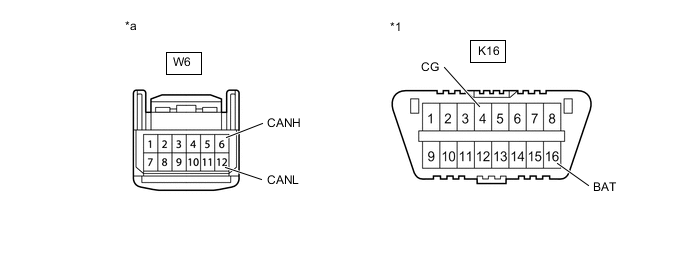
*1 DLC3 - - *a Front view of wire harness connector
(to Forward Recognition Camera)
- - -
Measure the resistance according to the value(s) in the table below.
Standard Resistance Tester Connection Condition Specified Condition W6-6 (CANH) - K16-4 (CG) Cable disconnected from negative (-) battery terminal 200 Ω or higher W6-12 (CANL) - K16-4 (CG) Cable disconnected from negative (-) battery terminal 200 Ω or higher W6-6 (CANH) - K16-16 (BAT) Cable disconnected from negative (-) battery terminal 6 kΩ or higher W6-12 (CANL) - K16-16 (BAT) Cable disconnected from negative (-) battery terminal 6 kΩ or higher -
Connect the W6 forward recognition camera connector.
Result Proceed to OK NG
OK
REPLACE FORWARD RECOGNITION CAMERA Click here
NG
-
-
CHECK FOR SHORT IN CAN BUS LINE (NO. 6 CAN JUNCTION CONNECTOR)
-
Disconnect the No. 6 CAN junction connector.
*1 DLC3 - - *a Front view of wire harness connector
(to No. 1 CAN junction connector)
*b to Forward Recognition Camera *c to Driving Support ECU Assembly *d to Millimeter Wave Radar Sensor Assembly -
Measure the resistance according to the value(s) in the table below.
Standard Resistance Tester Connection Condition Specified Condition Connected to K108-19 (CANL) - K16-4 (CG) Cable disconnected from negative (-) battery terminal 200 Ω or higher Forward Recognition Camera K108-8 (CANH) - K16-4 (CG) K108-19 (CANL) - K16-16 (BAT) 6 kΩ or higher K108-8 (CANH) - K16-16 (BAT) K108-9 (CA1P) - K16-4 (CG) Cable disconnected from negative (-) battery terminal 200 Ω or higher Driving Support ECU Assembly K108-20 (CA1N) - K16-4 (CG) K108-9 (CA1P) - K16-16 (BAT) 6 kΩ or higher K108-20 (CA1N) - K16-16 (BAT) K108-11 (CA1P) - K16-4 (CG) Cable disconnected from negative (-) battery terminal 200 Ω or higher Millimeter Wave Radar Sensor Assembly K108-22 (CA1N) - K16-4 (CG) K108-11 (CA1P) - K16-16 (BAT) 6 kΩ or higher K108-22 (CA1N) - K16-16 (BAT) -
Connect the K108 No. 6 CAN junction connector.
Result Result Proceed to OK A NG (Forward Recognition Camera Main Line) B NG (Millimeter Wave Radar Sensor Assembly) C NG (Driving Support ECU Assembly Branch Line) D
A
REPLACE NO. 6 CAN JUNCTION CONNECTOR
B
REPAIR OR REPLACE CAN BUS MAIN LINE OR CONNECTOR (NO. 6 CAN JUNCTION CONNECTOR - FORWARD RECOGNITION CAMERA)
D
CHECK FOR SHORT IN CAN BUS LINE (DRIVING SUPPORT ECU ASSEMBLY) Click here
C
-
-
CHECK FOR SHORT IN CAN BUS LINE (MILLIMETER WAVE RADAR SENSOR ASSEMBLY)
-
Disconnect the millimeter wave radar sensor assembly connector.
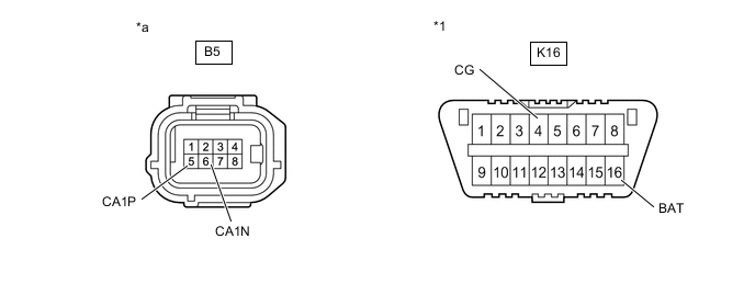
*1 DLC3 - - *a Front view of wire harness connector
(to Millimeter Wave Radar Sensor Assembly)
- - -
Measure the resistance according to the value(s) in the table below.
Standard Resistance Tester Connection Condition Specified Condition B5-5 (CA1P) - K16-4 (CG) Cable disconnected from negative (-) battery terminal 200 Ω or higher B5-6 (CA1N) - K16-4 (CG) Cable disconnected from negative (-) battery terminal 200 Ω or higher B5-5 (CA1P) - K16-16 (BAT) Cable disconnected from negative (-) battery terminal 6 kΩ or higher B5-6 (CA1N) - K16-16 (BAT) Cable disconnected from negative (-) battery terminal 6 kΩ or higher -
Connect the B5 millimeter wave radar sensor assembly connector.
Result Proceed to OK NG
OK
REPLACE MILLIMETER WAVE RADAR SENSOR ASSEMBLY Click here
NG
REPAIR OR REPLACE CAN BUS MAIN LINE OR CONNECTOR (NO. 6 CAN JUNCTION CONNECTOR - MILLIMETER WAVE RADAR SENSOR ASSEMBLY)
-
-
CHECK FOR SHORT IN CAN BUS LINE (DRIVING SUPPORT ECU ASSEMBLY)
-
Disconnect the driving support ECU assembly connector.
*1 DLC3 - - *a Front view of wire harness connector
(to Driving Support ECU Assembly)
- - -
Measure the resistance according to the value(s) in the table below.
Standard Resistance Tester Connection Condition Specified Condition K4-8 (CA1P) - K16-4 (CG) Cable disconnected from negative (-) battery terminal 200 Ω or higher K4-9 (CA1N) - K16-4 (CG) Cable disconnected from negative (-) battery terminal 200 Ω or higher K4-8 (CA1P) - K16-16 (BAT) Cable disconnected from negative (-) battery terminal 6 kΩ or higher K4-9 (CA1N) - K16-16 (BAT) Cable disconnected from negative (-) battery terminal 6 kΩ or higher -
Connect the K4 driving support ECU assembly connector.
Result Proceed to OK NG
OK
REPLACE DRIVING SUPPORT ECU ASSEMBLY Click here
NG
REPAIR OR REPLACE CAN BUS BRANCH LINE OR CONNECTOR (NO. 6 CAN JUNCTION CONNECTOR - DRIVING SUPPORT ECU ASSEMBLY)
-
-
CHECK CAN BUS LINE (MALFUNCTION CONFIRMATION)
-
Turn the engine switch off.
-
Disconnect the cable from the negative (-) battery terminal.
-
*a Component with harness connected
(Driving Support ECU Assembly)
Measure the resistance according to the value(s) in the table below.
Standard Resistance Tester Connection Condition Specified Condition Result K4-8 (CA1P) - K4-9 (CA1N) Cable disconnected from negative (-) battery terminal 54 to 69 Ω Below 54 Ω:
Short circuit between bus lines
70 Ω or more:
Open circuit in a main bus line or driving support ECU assembly branch line
K4-8 (CA1P) - K4-28 (GND) Cable disconnected from negative (-) battery terminal 200 Ω or higher Below 200 Ω:
CANH ground short
K4-9 (CA1N) - K4-28 (GND) Cable disconnected from negative (-) battery terminal 200 Ω or higher Below 200 Ω:
CANH ground short
K4-8 (CA1P) - K4-7 (B) Cable disconnected from negative (-) battery terminal 6 kΩ or higher Below 6 kΩ:
CANH +B short
K4-9 (CA1N) - K4-7 (B) Cable disconnected from negative (-) battery terminal 6 kΩ or higher Below 6 kΩ:
CANH +B short
Result Result Proceed to OK A NG (Open circuit in main line or Driving support ECU assembly branch line) B NG (Short circuit between main lines) C NG (Short to +B or ground) D
B
CHECK FOR OPEN IN CAN BUS BRANCH LINES (DRIVING SUPPORT ECU ASSEMBLY) Click here
C
CHECK FOR SHORT BETWEEN CAN BUS LINES (FORWARD RECOGNITION CAMERA) Click here
D
CHECK FOR SHORT IN CAN BUS LINE (FORWARD RECOGNITION CAMERA (CAMERA SENSOR)) Click here
A
-
-
CHECK FOR DTCs (PRE-CRASH SAFETY SYSTEM)
-
Clear the DTCs.
Body Electrical > Pre-Crash 2 > Clear DTCs -
Perform the following procedure.
Tech Tips
If the following procedure is not performed, the previously output DTC cannot be detected.
-
Turn the engine switch on (IG) and wait 2 seconds or more.
-
-
Check for DTCs.
Body Electrical > Pre-Crash 2 > Trouble CodesResult Result Proceed to DTC U1002 is not output A DTC U1002 is output B
A
USE SIMULATION METHOD TO CHECK Click here
B
REPLACE DRIVING SUPPORT ECU ASSEMBLY Click here
-
-
CHECK FOR OPEN IN CAN BUS BRANCH LINES (DRIVING SUPPORT ECU ASSEMBLY)
-
*a Front view of wire harness connector
(to Driving Support ECU Assembly)
Disconnect the driving support ECU assembly connector.
-
Measure the resistance according to the value(s) in the table below.
Standard Resistance Tester Connection Condition Specified Condition K4-8 (CA1P) - K4-9 (CA1N) Cable disconnected from negative (-) battery terminal 108 to 132 Ω Tech Tips
If the resistance is between 108 and 132 Ω, there may be an open in a CAN bus main line. If the value is 132 Ω or more, there may be an open in a CAN bus branch line between the No. 6 CAN junction connector and the driving support ECU or a connector may be disconnected.
-
Connect the K4 driving support ECU assembly connector.
Result Proceed to OK NG
NG
CHECK FOR OPEN IN CAN BUS BRANCH LINES (DRIVING SUPPORT ECU ASSEMBLY) Click here
OK
-
-
CHECK FOR OPEN IN CAN BUS MAIN LINES (NO. 6 CAN JUNCTION CONNECTOR)
-
*a Front view of wire harness connector
(to No. 6 CAN Junction Connector)
*b to Forward Recognition Camera Disconnect the No. 6 CAN junction connector.
-
Measure the resistance according to the value(s) in the table below.
Standard Resistance Tester Connection Condition Specified Condition Connected to K108-19 (CANL) - K108-8 (CANH) Cable disconnected from negative (-) battery terminal 108 to 132 Ω Forward Recognition Camera K108-11 - K108-22 Cable disconnected from negative (-) battery terminal 108 to 132 Ω No. 1 CAN Junction Connector -
Connect the K108 No. 6 CAN junction connector.
Result Result Proceed to OK A NG (Forward Recognition Camera Main Line) B NG (No. 1 CAN Junction Connector Main Line) C
A
REPLACE NO. 6 CAN JUNCTION CONNECTOR
C
CHECK FOR OPEN IN CAN BUS MAIN LINES (MILLIMETER WAVE RADAR SENSOR ASSEMBLY) Click here
B
-
-
CHECK FOR OPEN IN CAN BUS MAIN LINES (FORWARD RECOGNITION CAMERA)
-
*a Front view of wire harness connector
(to Forward Recognition Camera)
Disconnect the forward recognition camera connector.
-
Measure the resistance according to the value(s) in the table below.
Standard Resistance Tester Connection Condition Specified Condition W6-6 (CANH) - W6-12 (CANL) Cable disconnected from negative (-) battery terminal 108 to 132 Ω -
Connect the W6 forward recognition camera connector.
Result Proceed to OK NG
OK
REPLACE FORWARD RECOGNITION CAMERA Click here
NG
REPAIR OR REPLACE CAN BUS MAIN LINE OR CONNECTOR (NO. 6 CAN JUNCTION CONNECTOR - FORWARD RECOGNITION CAMERA)
-
-
CHECK FOR OPEN IN CAN BUS MAIN LINES (MILLIMETER WAVE RADAR SENSOR ASSEMBLY)
-
*a Front view of wire harness connector
(to Millimeter Wave Radar Sensor Assembly)
Disconnect the millimeter wave radar sensor assembly connector.
-
Measure the resistance according to the value(s) in the table below.
Standard Resistance Tester Connection Condition Specified Condition B5-5 (CA1P) - B5-6 (CA1N) Cable disconnected from negative (-) battery terminal 108 to 132 Ω -
Connect the B5 millimeter wave radar sensor assembly connector.
Result Proceed to OK NG
OK
REPLACE MILLIMETER WAVE RADAR SENSOR ASSEMBLY Click here
NG
-
-
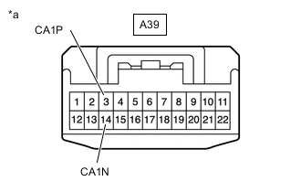
CHECK FOR OPEN IN CAN BUS MAIN LINES (NO. 1 CAN JUNCTION CONNECTOR)
-

*a Front view of wire harness connector
(to No. 1 CAN Junction Connector)
Disconnect the No. 1 CAN junction connector.
-
Measure the resistance according to the value(s) in the table below.
Standard Resistance Tester Connection Condition Specified Condition Connected to A39-4 - A39-15 Cable disconnected from negative (-) battery terminal 108 to 132 Ω No. 6 CAN Junction Connector A39-3 (CA1P) - A39-14 (CA1N) Cable disconnected from negative (-) battery terminal 108 to 132 Ω Millimeter Wave Radar Sensor Assembly -
Connect the A39 No. 1 CAN junction connector.
Result Result Proceed to OK A NG (No. 6 CAN Junction Connector Main Line) B NG (Millimeter Wave Radar Sensor Assembly Main Line) C
A
REPLACE NO. 1 CAN JUNCTION CONNECTOR
B
REPAIR OR REPLACE CAN BUS MAIN LINE OR CONNECTOR (NO. 1 CAN JUNCTION CONNECTOR - NO. 6 CAN JUNCTION CONNECTOR)
C
-
-
CHECK FOR OPEN IN CAN BUS BRANCH LINES (MILLIMETER WAVE RADAR SENSOR ASSEMBLY)
-

*a Front view of wire harness connector
(to Millimeter Wave Radar Sensor Assembly)
Disconnect the millimeter wave radar sensor assembly connector.
-
*a Front view of wire harness connector
(to No. 1 CAN Junction Connector)
Disconnect the No. 1 CAN junction connector.
-
Measure the resistance according to the value(s) in the table below.
Standard Resistance Tester Connection Condition Specified Condition A39-3 (CA1P) - B5-5 (CA1P) Cable disconnected from negative (-) battery terminal Below 1 Ω A39-14 (CA1N) - B5-6 (CA1N) Cable disconnected from negative (-) battery terminal Below 1 Ω -
Connect the A39 No. 1 CAN junction connector.
-
Connect the B5 millimeter wave radar sensor assembly connector.
Result Proceed to OK NG
OK
REPLACE NO. 1 CAN JUNCTION CONNECTOR
NG
REPAIR OR REPLACE CAN BUS BRANCH WIRE (NO. 1 CAN JUNCTION CONNECTOR - MILLIMETER WAVE RADAR SENSOR ASSEMBLY)
-
-
CHECK FOR OPEN IN CAN BUS BRANCH LINES (DRIVING SUPPORT ECU ASSEMBLY)
-
*a Front view of wire harness connector
(to Driving Support ECU Assembly)
Disconnect the driving support ECU assembly connector.
-
*a Front view of wire harness connector
(to No. 6 CAN Junction Connector)
Disconnect the No. 6 CAN junction connector.
-
Measure the resistance according to the value(s) in the table below.
Standard Resistance Tester Connection Condition Specified Condition K108-9 (CA1P) - K4-8 (CA1P) Cable disconnected from negative (-) battery terminal Below 1 Ω K108-20 (CA1N) - K4-9 (CA1N) Cable disconnected from negative (-) battery terminal Below 1 Ω -
Connect the K108 No. 6 CAN junction connector.
-
Connect the K4 driving support ECU assembly connector.
Result Proceed to OK NG
OK
REPLACE NO. 6 CAN JUNCTION CONNECTOR
NG
REPAIR OR REPLACE CAN BUS BRANCH WIRE (NO. 6 CAN JUNCTION CONNECTOR - DRIVING SUPPORT ECU ASSEMBLY)
-
-
CHECK FOR SHORT BETWEEN CAN BUS LINES (FORWARD RECOGNITION CAMERA)
-
*a Front view of wire harness connector
(to Forward Recognition Camera)
Disconnect the forward recognition camera connector.
-
Measure the resistance according to the value(s) in the table below.
Standard Resistance Tester Connection Condition Specified Condition W6-6 (CANH) - W6-12 (CANL) Cable disconnected from negative (-) battery terminal 108 to 132 Ω -
Connect the W6 forward recognition camera connector.
Result Proceed to OK NG
OK
REPLACE FORWARD RECOGNITION CAMERA Click here
NG
-
-
CHECK FOR SHORT BETWEEN CAN BUS LINES (NO. 6 CAN JUNCTION CONNECTOR)
-
*a Front view of wire harness connector
(to No. 6 CAN junction connector)
*b to Forward Recognition Camera *c to Driving Support ECU Assembly Disconnect the No. 6 CAN junction connector.
-
Measure the resistance according to the value(s) in the table below.
Standard Resistance Tester Connection Condition Specified Condition Connected to K108-19 (CANL) - K108-8 (CANH) Cable disconnected from negative (-) battery terminal 108 to 132 Ω Forward Recognition Camera K108-11 - K108-22 Cable disconnected from negative (-) battery terminal 108 to 132 Ω No. 1 CAN Junction Connector K108-9 (CA1P) - K108-20 (CA1N) Cable disconnected from negative (-) battery terminal 200 Ω or higher Driving Support ECU Assembly -
Connect the K108 No. 6 CAN junction connector.
Result Result Proceed to OK A NG (Forward Recognition Camera Main Line) B NG (No. 1 CAN Junction Connector Main Line) C NG (Driving Support ECU Assembly Branch Line) D
A
REPLACE NO. 6 CAN JUNCTION CONNECTOR
B
REPAIR OR REPLACE CAN BUS MAIN LINE OR CONNECTOR (NO. 6 CAN JUNCTION CONNECTOR - FORWARD RECOGNITION CAMERA)
D
CHECK FOR SHORT BETWEEN CAN BUS LINES (DRIVING SUPPORT ECU ASSEMBLY) Click here
C
-
-
CHECK FOR SHORT BETWEEN CAN BUS LINES (NO. 1 CAN JUNCTION CONNECTOR)
-
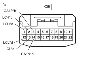
*a Front view of wire harness connector
(to No. 1 CAN junction connector)
*b to Millimeter Wave Radar Sensor Assembly *c to Headlight Control Computer Assembly LH *d to Headlight Control Computer Assembly RH Disconnect the No. 1 CAN junction connector.
-
Measure the resistance according to the value(s) in the table below.
Standard Resistance Tester Connection Condition Specified Condition Connected to K39-3 (CA1P) - K39-14 (CA1N) Cable disconnected from negative (-) battery terminal 108 to 132 Ω Millimeter Wave Radar Sensor Assembly K39-4 - K39-15 Cable disconnected from negative (-) battery terminal 108 to 132 Ω No. 6 CAN Junction Connector K39-2 (LCH) - K39-13 (LCL) Cable disconnected from negative (-) battery terminal 200 Ω or higher AHS Light Control ECU Sub-assembly LH K39-1 (LCH) - K39-12 (LCL) Cable disconnected from negative (-) battery terminal 200 Ω or higher AHS Light Control ECU Sub-assembly RH -
Connect the K39 No. 1 CAN junction connector.
Result Result Proceed to OK A NG (Millimeter Wave Radar Sensor Assembly Main Line) B NG (No. 6 CAN Junction Connector Main Line) C NG (Headlight Control Computer Assembly LH Branch Line) D NG (Headlight Control Computer Assembly RH Branch Line) E
A
REPLACE NO. 1 CAN JUNCTION CONNECTOR
C
REPAIR OR REPLACE CAN BUS MAIN LINE OR CONNECTOR (NO. 1 CAN JUNCTION CONNECTOR - NO. 6 CAN JUNCTION CONNECTOR)
D
CHECK FOR SHORT BETWEEN CAN BUS LINES (HEADLIGHT LIGHT CONTROL ECU SUB-ASSEMBLY RH) Click here
E
CHECK FOR SHORT BETWEEN CAN BUS LINES (HEADLIGHT LIGHT CONTROL ECU SUB-ASSEMBLY RH) Click here
B
-
-
CHECK FOR SHORT BETWEEN CAN BUS LINES (MILLIMETER WAVE RADAR SENSOR ASSEMBLY)
-
*a Front view of wire harness connector
(to Millimeter Wave Radar Sensor Assembly)
Disconnect the millimeter wave radar sensor assembly connector.
-
Measure the resistance according to the value(s) in the table below.
Standard Resistance Tester Connection Condition Specified Condition B5-5 (CA1P) - B5-6 (CA1N) Cable disconnected from negative (-) battery terminal 108 to 132 Ω -
Connect the B5 millimeter wave radar sensor assembly connector.
Result Proceed to OK NG
OK
REPLACE MILLIMETER WAVE RADAR SENSOR ASSEMBLY Click here
NG
REPAIR OR REPLACE CAN BUS MAIN LINE OR CONNECTOR (NO. 1 CAN JUNCTION CONNECTOR - MILLIMETER WAVE RADAR SENSOR ASSEMBLY)
-
-
CHECK FOR SHORT BETWEEN CAN BUS LINES (DRIVING SUPPORT ECU ASSEMBLY)
-
*a Front view of wire harness connector
(to Driving Support ECU Assembly)
Disconnect the driving support ECU assembly connector.
-
Measure the resistance according to the value(s) in the table below.
Standard Resistance Tester Connection Condition Specified Condition K4-8 (CA1P) - K4-9 (CA1N) Cable disconnected from negative (-) battery terminal 54 to 69 Ω -
Connect the K4 driving support ECU assembly connector.
Result Proceed to OK NG
OK
REPLACE DRIVING SUPPORT ECU ASSEMBLY Click here
NG
REPAIR OR REPLACE CAN BUS BRANCH LINE OR CONNECTOR (NO. 1 CAN JUNCTION CONNECTOR - DRIVING SUPPORT ECU ASSEMBLY)
-
-
CHECK FOR SHORT BETWEEN CAN BUS LINES (HEADLIGHT LIGHT CONTROL ECU SUB-ASSEMBLY RH)
-
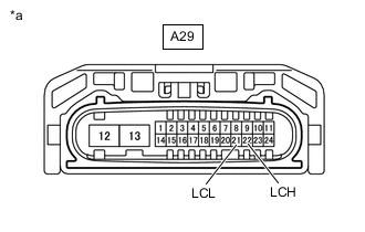
*a Front view of wire harness connector
(to Headlight Control Computer Assembly LH)
Disconnect the headlight control computer assembly LH connector.
-
Measure the resistance according to the value(s) in the table below.
Standard Resistance Tester Connection Condition Specified Condition A29-22 (LCH) - A29-21 (LCL) Cable disconnected from negative (-) battery terminal 54 to 69 Ω -
Connect the A29 headlight control computer assembly LH connector.
Result Proceed to OK NG
OK
REPLACE HEADLIGHT LIGHT CONTROL ECU SUB-ASSEMBLY LH Click here
NG
REPAIR OR REPLACE CAN BUS BRANCH LINE OR CONNECTOR (NO. 1 CAN JUNCTION CONNECTOR - HEADLIGHT LIGHT CONTROL ECU SUB-ASSEMBLY LH)
-
-
CHECK FOR SHORT BETWEEN CAN BUS LINES (HEADLIGHT LIGHT CONTROL ECU SUB-ASSEMBLY RH)
-
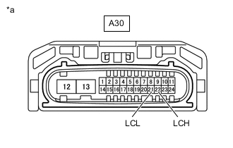
*a Front view of wire harness connector
(to Headlight Control Computer Assembly RH)
Disconnect the headlight control computer assembly RH connector.
-
Measure the resistance according to the value(s) in the table below.
Standard Resistance Tester Connection Condition Specified Condition A30-22 (LCH) - A30-21 (LCL) Cable disconnected from negative (-) battery terminal 54 to 69 Ω -
Connect the A30 headlight control computer assembly RH connector.
Result Proceed to OK NG
OK
Use the same procedure as for the headlight light control ECU sub-assembly LH. Click here
NG
REPAIR OR REPLACE CAN BUS BRANCH LINE OR CONNECTOR (NO. 1 CAN JUNCTION CONNECTOR - HEADLIGHT LIGHT CONTROL ECU SUB-ASSEMBLY RH)
-
-
CHECK FOR SHORT IN CAN BUS LINE (FORWARD RECOGNITION CAMERA (CAMERA SENSOR))
-
Disconnect the forward recognition camera connector.
*1 DLC3 - - *a Front view of wire harness connector
(to Forward Recognition Camera)
- - -
Measure the resistance according to the value(s) in the table below.
Standard Resistance Tester Connection Condition Specified Condition W6-6 (CANH) - K16-4 (CG) Cable disconnected from negative (-) battery terminal 200 Ω or higher W6-12 (CANL) - K16-4 (CG) Cable disconnected from negative (-) battery terminal 200 Ω or higher W6-6 (CANH) - K16-16 (BAT) Cable disconnected from negative (-) battery terminal 6 kΩ or higher W6-12 (CANL) - K16-16 (BAT) Cable disconnected from negative (-) battery terminal 6 kΩ or higher -
Connect the W6 forward recognition camera connector.
Result Proceed to OK NG
OK
REPLACE FORWARD RECOGNITION CAMERA Click here
NG
-
-
CHECK FOR SHORT IN CAN BUS LINE (NO. 6 CAN JUNCTION CONNECTOR)
-
Disconnect the No. 6 CAN junction connector.
*1 DLC3 - - *a Front view of wire harness connector
(to No. 1 CAN junction connector)
*b to Forward Recognition Camera *c to Driving Support ECU Assembly - - -
Measure the resistance according to the value(s) in the table below.
Standard Resistance Tester Connection Condition Specified Condition Connected to K108-19 (CANL) - K16-4 (CG) Cable disconnected from negative (-) battery terminal 200 Ω or higher Forward Recognition Camera K108-8 (CANH) - K16-4 (CG) K108-19 (CANL) - K16-16 (BAT) 6 kΩ or higher K108-8 (CANH) - K16-16 (BAT) K108-9 (CA1P) - K16-4 (CG) Cable disconnected from negative (-) battery terminal 200 Ω or higher Driving Support ECU Assembly K108-20 (CA1N) - K16-4 (CG) K108-9 (CA1P) - K16-16 (BAT) 6 kΩ or higher K108-20 (CA1N) - K16-16 (BAT) K108-11 - K16-4 (CG) Cable disconnected from negative (-) battery terminal 200 Ω or higher No. 1 CAN Junction Connector K108-22 - K16-4 (CG) K108-11 - K16-16 (BAT) 6 kΩ or higher K108-22 - K16-16 (BAT) -
Connect the K108 No. 6 CAN junction connector.
Result Result Proceed to OK A NG (Forward Recognition Camera Main Line) B NG (No. 1 CAN Junction Connector Main Line) C NG (Driving Support ECU Assembly Branch Line) D
A
REPLACE NO. 6 CAN JUNCTION CONNECTOR
B
REPAIR OR REPLACE CAN BUS MAIN LINE OR CONNECTOR (NO. 6 CAN JUNCTION CONNECTOR - FORWARD RECOGNITION CAMERA)
D
CHECK FOR SHORT IN CAN BUS LINE (DRIVING SUPPORT ECU ASSEMBLY) Click here
C
-
-
CHECK FOR SHORT IN CAN BUS LINE (MILLIMETER WAVE RADAR SENSOR ASSEMBLY)
-
Disconnect the millimeter wave radar sensor assembly connector.
*1 DLC3 - - *a Front view of wire harness connector
(to Millimeter Wave Radar Sensor Assembly)
- - -
Measure the resistance according to the value(s) in the table below.
Standard Resistance Tester Connection Condition Specified Condition B5-5 (CA1P) - K16-4 (CG) Cable disconnected from negative (-) battery terminal 200 Ω or higher B5-6 (CA1N) - K16-4 (CG) Cable disconnected from negative (-) battery terminal 200 Ω or higher B5-5 (CA1P) - K16-16 (BAT) Cable disconnected from negative (-) battery terminal 6 kΩ or higher B5-6 (CA1N) - K16-16 (BAT) Cable disconnected from negative (-) battery terminal 6 kΩ or higher -
Connect the B5 millimeter wave radar sensor assembly connector.
Result Proceed to OK NG
OK
REPLACE MILLIMETER WAVE RADAR SENSOR ASSEMBLY Click here
NG
-
-
CHECK FOR SHORT IN CAN BUS LINE (NO. 1 CAN JUNCTION CONNECTOR)
-
Disconnect the No. 1 CAN junction connector.
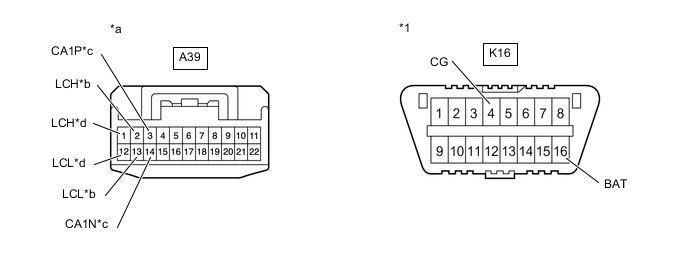
*1 DLC3 - - *a Front view of wire harness connector
(to No. 1 CAN junction connector)
*b to Headlight Control Computer Assembly LH *c to Millimeter Wave Radar Sensor Assembly *d to Headlight Control Computer Assembly RH -
Measure the resistance according to the value(s) in the table below.
Standard Resistance Tester Connection Condition Specified Condition Connected to A39-3 (CA1P) - K16-4 (CG) Cable disconnected from negative (-) battery terminal 200 Ω or higher Millimeter Wave Radar Sensor Assembly A39-14 (CA1N) - K16-4 (CG) A39-3 (CA1P) - K16-16 (BAT) 6 kΩ or higher A39-14 (CA1N) - K16-16 (BAT) A39-4 - K16-4 (CG) Cable disconnected from negative (-) battery terminal 200 Ω or higher No. 6 CAN Junction Connector A39-15 - K16-4 (CG) A39-4 - K16-16 (BAT) 6 kΩ or higher A39-15 - K16-16 (BAT) A39-2 (LCH) - K16-4 (CG) Cable disconnected from negative (-) battery terminal 200 Ω or higher Headlight Control Computer Assembly LH A39-13 (LCL) - K16-4 (CG) A39-2 (LCH) - K16-16 (BAT) 6 kΩ or higher A39-13 (LCL) - K16-16 (BAT) A39-1 (LCH) - K16-4 (CG) Cable disconnected from negative (-) battery terminal 200 Ω or higher Headlight Control Computer Assembly RH A39-12 (LCL) - K16-4 (CG) A39-1 (LCH) - K16-16 (BAT) 6 kΩ or higher A39-12 (LCL) - K16-16 (BAT) -
Connect the A39 No. 1 CAN junction connector.
Result Result Proceed to OK A NG (Millimeter Wave Radar Sensor Assembly Main Line) B NG (No. 6 CAN Junction Connector Main Line) C NG (Headlight Control Computer Assembly LH Branch Line) D NG (Headlight Control Computer Assembly RH Branch Line) E
A
REPLACE NO. 1 CAN JUNCTION CONNECTOR
B
REPAIR OR REPLACE CAN BUS MAIN LINE OR CONNECTOR (NO. 1 CAN JUNCTION CONNECTOR - MILLIMETER WAVE RADAR SENSOR ASSEMBLY)
C
REPAIR OR REPLACE CAN BUS MAIN LINE OR CONNECTOR (NO. 1 CAN JUNCTION CONNECTOR - NO. 6 CAN JUNCTION CONNECTOR)
D
CHECK FOR SHORT IN CAN BUS LINE (HEADLIGHT LIGHT CONTROL ECU SUB-ASSEMBLY LH) Click here
E
CHECK FOR SHORT IN CAN BUS LINE (HEADLIGHT LIGHT CONTROL ECU SUB-ASSEMBLY RH) Click here
-
-
CHECK FOR SHORT IN CAN BUS LINE (DRIVING SUPPORT ECU ASSEMBLY)
-
Disconnect the driving support ECU assembly connector.
*1 DLC3 - - *a Front view of wire harness connector
(to Driving Support ECU Assembly)
- - -
Measure the resistance according to the value(s) in the table below.
Standard Resistance Tester Connection Condition Specified Condition K4-8 (CA1P) - K16-4 (CG) Cable disconnected from negative (-) battery terminal 200 Ω or higher K4-9 (CA1N) - K16-4 (CG) Cable disconnected from negative (-) battery terminal 200 Ω or higher K4-8 (CA1P) - K16-16 (BAT) Cable disconnected from negative (-) battery terminal 6 kΩ or higher K4-9 (CA1N) - K16-16 (BAT) Cable disconnected from negative (-) battery terminal 6 kΩ or higher -
Connect the K4 driving support ECU assembly connector.
Result Proceed to OK NG
OK
REPLACE DRIVING SUPPORT ECU ASSEMBLY Click here
NG
REPAIR OR REPLACE CAN BUS BRANCH LINE OR CONNECTOR (NO. 1 CAN JUNCTION CONNECTOR - DRIVING SUPPORT ECU ASSEMBLY)
-
-
CHECK FOR SHORT IN CAN BUS LINE (HEADLIGHT LIGHT CONTROL ECU SUB-ASSEMBLY LH)
-
Disconnect the headlight light control ECU sub-assembly LH connector.
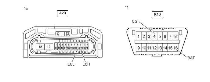
*1 DLC3 - - *a Front view of wire harness connector
(to AHS Light Control ECU Sub-assembly LH)
- - -
Measure the resistance according to the value(s) in the table below.
Standard Resistance Tester Connection Condition Specified Condition A29-22 (LCH) - K16-4 (CG) Cable disconnected from negative (-) battery terminal 200 Ω or higher A29-21 (LCL) - K16-4 (CG) Cable disconnected from negative (-) battery terminal 200 Ω or higher A29-22 (LCH) - K16-16 (BAT) Cable disconnected from negative (-) battery terminal 6 kΩ or higher A29-21 (LCL) - K16-16 (BAT) Cable disconnected from negative (-) battery terminal 6 kΩ or higher -
Connect the A29 headlight light control ECU sub-assembly LH connector.
Result Proceed to OK NG
OK
REPLACE HEADLIGHT LIGHT CONTROL ECU SUB-ASSEMBLY LH Click here
NG
REPAIR OR REPLACE CAN BUS BRANCH LINE OR CONNECTOR (NO. 1 CAN JUNCTION CONNECTOR - HEADLIGHT LIGHT CONTROL ECU SUB-ASSEMBLY LH)
-
-
CHECK FOR SHORT IN CAN BUS LINE (HEADLIGHT LIGHT CONTROL ECU SUB-ASSEMBLY RH)
-
Disconnect the headlight light control ECU sub-assembly RH connector.

*1 DLC3 - - *a Front view of wire harness connector
(to AHS Light Control ECU Sub-assembly RH)
- - -
Measure the resistance according to the value(s) in the table below.
Standard Resistance Tester Connection Condition Specified Condition A30-22 (LCH) - K16-4 (CG) Cable disconnected from negative (-) battery terminal 200 Ω or higher A30-21 (LCL) - K16-4 (CG) Cable disconnected from negative (-) battery terminal 200 Ω or higher A30-22 (LCH) - K16-16 (BAT) Cable disconnected from negative (-) battery terminal 6 kΩ or higher A30-21 (LCL) - K16-16 (BAT) Cable disconnected from negative (-) battery terminal 6 kΩ or higher -
Connect the A30 headlight light control ECU sub-assembly RH connector.
Result Proceed to OK NG
OK
Use the same procedure as for the headlight light control ECU sub-assembly LH. Click here
NG
REPAIR OR REPLACE CAN BUS BRANCH LINE OR CONNECTOR (NO. 1 CAN JUNCTION CONNECTOR - HEADLIGHT LIGHT CONTROL ECU SUB-ASSEMBLY RH)
-