SPIRAL CABLE INSTALLATION
PROCEDURE
-
INSPECT SPIRAL CABLE WITH SENSOR SUB-ASSEMBLY
-
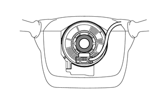
Check that the spiral cable sub-assembly is center position.
OK The connector is at the top. The matchmarks are aligned. The top of the flat cable U-turn can be checked from the check window. 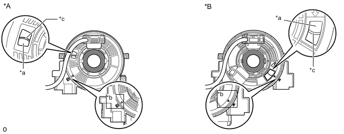
*A w/o Steering Heater *B w/ Steering Heater *a Check Window *b Matchmark *c Top of Flat Cable U-turn - - -
If the spiral cable sub-assembly is not centered, center it.
Note
Failure to observe the following precautions may result in damage to the spiral cable sub-assembly.
-
When rotating the spiral cable sub-assembly, make sure to push on the interlock to release the interlock.
-
Do not turn the spiral cable sub-assembly using the airbag wire harness.
-
Do not forcibly rotate the part.
-
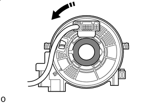

Interlock 
Counterclockwise While pushing on the interlock indicated in the illustration. Make sure to rotate the spiral cable sub-assembly counterclockwise slowly by hand until it stops.
Note
Make sure to rotate the spiral cable sub-assembly counterclockwise. If rotated clockwise, it may be damaged or centering may no longer be possible.
Tech Tips
The interlock operates at the top and bottom of the connector.
-
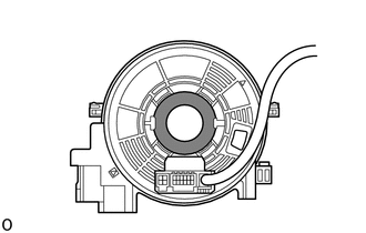
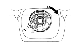
If the spiral cable sub-assembly stops rotating and the connector has moved past the bottom, return the connector to the bottom as shown in the illustration.
-
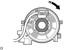
Interlock Clockwise While pushing on the interlock, rotate the spiral cable sub-assembly clockwise approximately 2.5 times to move the connector from the bottom to the top.
Note
If the connector is rotated clockwise from the bottom 5 times or more, the spiral cable sub-assembly may be damaged.
Tech Tips
The interlock operates at the top and bottom of the connector.
-
Check that the spiral cable sub-assembly is center position.
OK The connector is at the top. The matchmarks are aligned. The top of the flat cable U-turn can be checked from the check window.
*A w/o Steering Heater *B w/ Steering Heater *a Check Window *b Matchmark *c Top of Flat Cable U-turn - - Note
If the spiral cable sub-assembly cannot be centered, it is possible that the spiral cable sub-assembly is broken. Replace the spiral cable sub-assembly with a new one.
-
-
-
INSTALL SPIRAL CABLE WITH SENSOR SUB-ASSEMBLY
Note
-
Do not replace the spiral cable with the battery connected and the engine switch on (IG).
-
Do not rotate the spiral cable with the battery connected and the engine switch on (IG).
-
Ensure that the steering wheel is installed and aligned straight when inspecting the steering sensor.
-
Check that the engine switch is off.
-
Check that the cable is disconnected from the negative (-) battery terminal.
CAUTION:
-
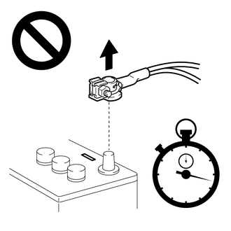
Wait at least 90 seconds after disconnecting the cable from the negative (-) battery terminal to disable the SRS system.
-
If the airbag deploys for any reason, it may cause a serious accident.
-
-
Check that the front wheels are facing straight ahead.
-
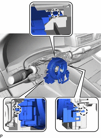
Engage the claws to install the spiral cable with sensor sub-assembly.
Note
When replacing the spiral cable with sensor sub-assembly with a new one, remove the lock pin before installing the steering wheel assembly.
-
Connect the connectors.
-
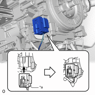
*a Slider Connect the airbag connector and check that the slider is in the lock position.
Note
When connecting any airbag connector, take care not to damage the airbag wire harness.
-
-
INSTALL STEERING COLUMN COVER
-
TURN FRONT WHEELS TO FACE STRAIGHT AHEAD
-
ADJUST SPIRAL CABLE WITH SENSOR SUB-ASSEMBLY
Note
Do not adjust the spiral cable with the battery connected and the engine switch on (IG).
-
Check that the engine switch is off.
-
Check that the cable is disconnected from the negative (-) battery terminal.
CAUTION:
-
Wait at least 90 seconds after disconnecting the cable from the negative (-) battery terminal to disable the SRS system.
-
If the airbag deploys for any reason, it may cause a serious accident.
-
-
Check that the spiral with sensor cable sub-assembly is center position.
OK The connector is at the top. The matchmarks are aligned. The top of the flat cable U-turn can be checked from the check window. 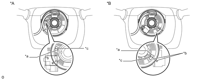
*A w/o Steering Heater *B w/ Steering Heater *a Check Window *b Matchmark *c Top of Flat Cable U-turn - - -
If the spiral with sensor cable sub-assembly is not centered, center it.
Note
Failure to observe the following precautions may result in damage to the spiral with sensor cable sub-assembly.
-
When rotating the spiral with sensor cable sub-assembly, make sure to push on the interlock to release the interlock.
-
Do not turn the spiral with sensor cable sub-assembly using the airbag wire harness.
-
Do not forcibly rotate the part.
-
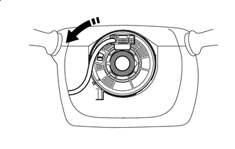
Interlock Counterclockwise While pushing on the interlock indicated in the illustration. Make sure to rotate the spiral with sensor cable sub-assembly counterclockwise slowly by hand until it stops.
Note
If the connector is rotated clockwise from the bottom 5 times or more, the spiral with sensor cable sub-assembly may be damaged.
Tech Tips
The interlock operates at the top and bottom of the connector.
-
If the spiral with sensor cable sub-assembly stops rotating and the connector has moved past the bottom, return the connector to the bottom as shown in the illustration.
-
Interlock Clockwise While pushing on the interlock, rotate the spiral with sensor cable sub-assembly clockwise approximately 2.5 times to move the connector from the bottom to the top.
Note
If the connector is rotated clockwise from the bottom 5 times or more, the spiral with sensor cable sub-assembly may be damaged.
Tech Tips
The interlock operates at the top and bottom of the connector.
-
Check that the spiral with sensor cable sub-assembly is center position.
OK The connector is at the top. The matchmarks are aligned. The top of the flat cable U-turn can be checked from the check window.
*A w/o Steering Heater *B w/ Steering Heater *a Check Window *b Matchmark *c Top of Flat Cable U-turn - - Note
If the spiral with sensor cable sub-assembly cannot be centered, it is possible that the spiral cable sub-assembly is broken. Replace the spiral cable sub-assembly with a new one.
-
-
-
INSTALL STEERING WHEEL ASSEMBLY
-
ENABLE AUTOAWAY/RETURN FUNCTION
-
Restore the autoaway/return function setting to the previous condition by changing the customize parameter.
-