METER / GAUGE SYSTEM Meter Illumination is Always Dark
DESCRIPTION
The combination meter assembly receives signals from this circuit to adjust the illumination of the combination meter assembly. The combination meter assembly sets the illumination level based on the user operation of the light control rheostat switch.
WIRING DIAGRAM
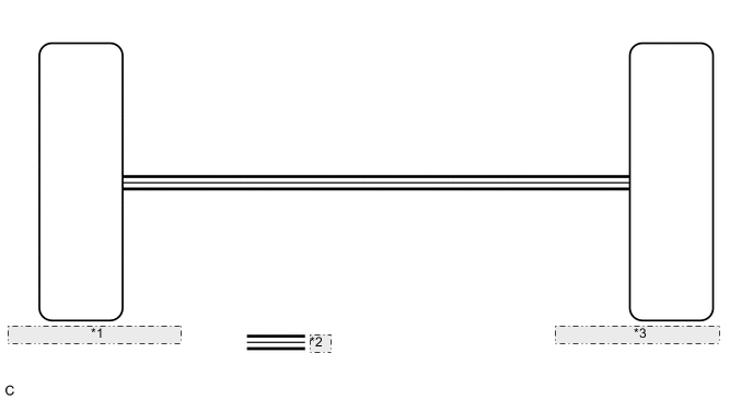
| *1 | Main Body ECU (Multiplex Network Body ECU) |
| *2 | CAN Communication Line |
| *3 | Combination Meter Assembly |
CAUTION / NOTICE / HINT
Note
Before replacing the main body ECU (multiplex network body ECU), refer to Registration.
Tech Tips
-
The meter illumination dims when the taillights are turned on.
-
Setting the meter illumination level to maximum brightness cancels the above dimming of the meter illumination.
-
Setting the meter illumination level to minimum brightness turns off the meter illumination.
-
The automatic light control sensor sensitivity can be customized.
for Triple Beam Headlight: Click here
for Single Beam Headlight: Click here
PROCEDURE
-
CHECK CAN COMMUNICATION SYSTEM
-
Check if CAN communication DTCs are output.
for LHD: Click here
for RHD: Click here
Result Result Proceed to CAN communication DTCs are not output. A CAN communication DTCs are output. B
B 
GO TO CAN COMMUNICATION SYSTEM for LHD: Click here
GO TO CAN COMMUNICATION SYSTEM for RHD: Click hereA 
-
-
CHECK FOR DTC
-
Check if lighting system DTCs are output.
Body Electrical > Main Body > Trouble CodesResult Result Proceed to DTC B1244 is not output. A DTC B1244 is output. B
B
GO TO DTC B1244 Click here
A
-
-
REPLACE COMBINATION METER ASSEMBLY
-
Replace the combination meter assembly with a new or known good one.
OK The operation of the combination meter assembly returns to normal. Result Proceed to OK NG
OK
END
NG
REPLACE MAIN BODY ECU (MULTIPLEX NETWORK BODY ECU) Click here
-