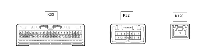
METER / GAUGE SYSTEM TERMINALS OF ECU
-
COMBINATION METER ASSEMBLY
-
Disconnect the combination meter assembly connectors.
-
Measure the voltage on the wire harness side connector according to the value(s) in the table below.
Terminal No. Wiring Color Terminal Description Condition Specified Condition K33-21 (IG+) - Body ground W - Body ground Engine switch signal Engine switch off Below 1 V Engine switch on (IG) 11 to 14 V K33-22 (B) - Body ground P - Body ground Battery Always 11 to 14 V K32-8 (B) - Body ground W - Body ground Battery Always 11 to 14 V If the result is not as specified, there may be a malfunction in the wire harness.
-
Measure the resistance on the wire harness side connector according to the value(s) in the table below.
Terminal No. (Symbol) Wiring Color Terminal Description Condition Specified Condition K33-18 (PIND) - Body ground P - Body ground Brake pad sensor signal Always Below 1 Ω If the result is not as specified, there may be a malfunction in the wire harness or pad wear indicator wire assembly.
-
Measure the resistance on the wire harness side connector according to the value(s) in the table below.
Terminal No. (Symbol) Wiring Color Terminal Description Condition Specified Condition K33-31 (ES) - Body ground W-B - Body ground Ground Always Below 1 Ω K33-40 (EP) - Body ground W-B - Body ground Ground Always Below 1 Ω If the result is not as specified, there may be a malfunction in the wire harness.
-
Reconnect the combination meter assembly connectors.
-
Measure the voltage and resistance according to the value(s) in the table below.
Terminal No. (Symbol) Wiring Color Terminal Description Condition Specified Condition K33-1 (GAGE) - K33-24 (GND) B - P Engine oil temperature signal Idling, Engine oil temperature 80 to 105°C (176 to 221°F) 1.24 to 1.94 V K33-2 (MSM+) - Body ground L - Body ground Steering pad switch assembly signal Engine switch on (IG), up, down, right, and left switches on steering pad switch assembly not pushed 4.8 to 5.2 V Engine switch on (IG), up, down, right, or left switch on steering pad switch assembly pushed Below 1 V K33-3 (MSTI) - Body ground V - Body ground Steering pad switch assembly signal Engine switch on (IG), enter, top and back switches on steering pad switch assembly not pushed 4.8 to 5.2 V Engine switch on (IG), enter, top or back switch on steering pad switch assembly pushed Below 1 V K33-4 (RSET) - Body ground G - Body ground ODO/TRIP switch signal Engine switch on (IG), ODO/TRIP switch not pushed 4 to 6 V Engine switch on (IG), ODO/TRIP switch pushed Below 1 V K33-9 (S) - Body ground Y - Body ground Oil pressure signal Idling 11 to 14 V Engine switch on (IG) Below 1 V K33-15 (OILW) - Body ground B - Body ground Engine oil level signal Engine switch on (IG), engine oil level not low 11 to 14 V Engine switch on (IG), engine oil level low Below 1 V K33-16 (WLVL) - Body ground GR - Body ground Washer fluid level signal Engine switch on (IG), washer fluid level not low 11 to 14 V Engine switch on (IG), washer fluid level low Below 1 V K33-17 (SW) - Body ground Y - Body ground Brake fluid level signal Engine switch on (IG), brake fluid level not low Below 1 V Engine switch on (IG), brake fluid level low 11 to 14 V K33-19 (+S) - Body ground SB - Body ground Speed signal for other system (Output) Engine switch on (IG), wheel being rotated Pulse generation (See waveform 1) K33-20 (SI) - Body ground V - Body ground Speed signal for other system (Input) Engine switch on (IG), wheel being rotated Pulse generation (See waveform 1) K33-25 (TR) - Body ground B - Body ground Light control rheostat switch signal Engine switch on (IG), up switch and down switch of trip switch not pushed 4 to 6 V Engine switch on (IG), up switch or down switch of trip switch pushed Below 1 V K33-27 (FR) - K33-28 (FE) BR - L Fuel level signal Engine switch on (IG), fuel level warning off Below 1 V Engine switch on (IG), fuel level warning on 4.5 to 9 V K33-29 (CANH) - Body ground Y - Body ground CAN communication line - - K33-30 (CANL) - Body ground W - Body ground CAN communication line - - K33-39 (ILL-) - Body ground W - Body ground Illumination signal Headlight dimmer switch off Below 1 V Headlight dimmer switch in tail or head position Pulse generation K32-2 (TX-) - Body ground V - Body ground Local bus communication line - - K32-3 (TX+) - Body ground W- Body ground Local bus communication line - - K32-4 (ER) - Body ground B - Body ground RH turn indicator light signal (Input) Engine switch on (IG), RH turn signal switch off 11 to 14 V Engine switch on (IG), RH turn signal switch on Below 1 V K32-5 (EL) - Body ground L - Body ground LH turn indicator light signal (Input) Engine switch on (IG), LH turn signal switch off 11 to 14 V Engine switch on (IG), LH turn signal switch on Below 1 V K32-7 (LR) - Body ground G - Body ground RH turn indicator light signal (Output) Engine switch on (IG), RH turn indicator light off Below 1 V Engine switch on (IG), RH turn indicator light blinking 11 to 14 V ←→ Below 1 V K32-11 (HZSW) - Body ground P - Body ground Hazard warning signal switch signal (Input) Engine switch on (IG), hazard warning signal switch not pressed 11 to 14 V Engine switch on (IG), hazard warning signal switch pressed Below 1 V K32-12 (HAZM) - Body ground SB - Body ground Hazard warning signal switch signal (Output) Engine switch on (IG), hazard warning signal switch not pressed 11 to 14 V Engine switch on (IG), hazard warning signal switch pressed Below 1 V K32-13 (LL) - Body ground Y - Body ground LH turn indicator light signal (Output) Engine switch on (IG), LH turn indicator light off Below 1 V Engine switch on (IG), LH turn indicator light blinking 11 to 14 V ←→ Below 1 V K120-1 (GVIF) - Body ground B - Body ground Video signal (Digital) - - If the result is not as specified, the combination meter assembly may be malfunctioning.
-
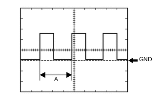
Waveform 1 (Reference):
Item Condition Tool setting 5 V/DIV., 20 ms./DIV. Vehicle condition Engine switch on (IG), wheel being rotated Tech Tips
When the system is functioning normally, one wheel revolution generates 4 pulses. As the vehicle speed increases, the width indicated by (A) in the illustration narrows.
-
-