HEADUP DISPLAY SYSTEM, Diagnostic DTC:B150A
| DTC Code | DTC Name |
|---|---|
| B150A | Lost Communication with HMI-LAN |
DESCRIPTION
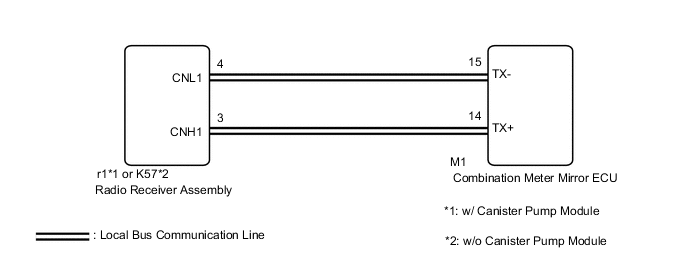
The combination meter mirror ECU receives signals from the radio receiver assembly via local bus communication and displays audio system and navigation system information on the headup display.
This DTC is stored when the combination meter mirror ECU cannot receive the signal.
| DTC No. | Detection Item | DTC Detection Condition | Trouble Area | Memory |
|---|---|---|---|---|
| B150A | Lost Communication with HMI-LAN | After the combination meter mirror ECU receives a registration information signal, which is sent by the radio receiver assembly when the engine switch is on (ACC), 1 or more times, the combination meter mirror ECU cannot receive the signal for 30 seconds or more. |
|
DTC stored |
WIRING DIAGRAM
PROCEDURE
-
CONFIRM MODEL
-
Choose the model to be inspected.
Result Result Proceed to w/ Navigation System A w/o Navigation System B
B 
CHECK FOR DTC Click here
A 
-
-
CHECK FOR DTC
-
Check if navigation system DTCs are output.
Body Electrical > Navigation System > Trouble CodesResult Result Proceed to Navigation system DTCs are not output. A Navigation system DTCs are output. B
A
GO TO STEP 4 Click here
B 
GO TO NAVIGATION SYSTEM Click here
-
-
CHECK FOR DTC
-
Check if audio and visual system DTCs are output.
-
for 12.3 Inch Display: Click here
-
for 8 Inch Display: Click here
Body Electrical > Navigation System > Trouble CodesResult Result Proceed to Audio and visual system DTCs are not output. A Audio and visual system DTCs are output. (for 12.3 Inch Display) B Audio and visual system DTCs are output. (for 8 Inch Display) C -
B
GO TO AUDIO AND VISUAL SYSTEM Click here
C
GO TO AUDIO AND VISUAL SYSTEM Click here
A
-
-
CHECK HARNESS AND CONNECTOR (COMBINATION METER MIRROR ECU - RADIO RECEIVER ASSEMBLY)
-
w/ Canister Pump Module
-
Disconnect the M1 combination meter mirror ECU connector.
-
Disconnect the r1 radio receiver assembly connector.
-
Measure the resistance according to the value(s) in the table below.
Standard Resistance Tester Connection Condition Specified Condition M1-15 (TX-) - r1-4 (CNL1) Always Below 1 Ω M1-14 (TX+) - r1-3 (CNH1) Always Below 1 Ω M1-15 (TX-) or r1-4 (CNL1) - Body ground Always 10 kΩ or higher M1-14 (TX+) or r1-3 (CNH1) - Body ground Always 10 kΩ or higher
-
-
w/o Canister Pump Module
-
Disconnect the M1 combination meter mirror ECU connector.
-
Disconnect the K57 radio receiver assembly connector.
-
Measure the resistance according to the value(s) in the table below.
Standard Resistance Tester Connection Condition Specified Condition M1-15 (TX-) - K57-4 (CNL1) Always Below 1 Ω M1-14 (TX+) - K57-3 (CNH1) Always Below 1 Ω M1-15 (TX-) or K57-4 (CNL1) - Body ground Always 10 kΩ or higher M1-14 (TX+) or K57-3 (CNH1) - Body ground Always 10 kΩ or higher
Result Proceed to OK NG -
NG
REPAIR OR REPLACE HARNESS OR CONNECTOR
OK
-
-
CHECK FOR DTC
-
Check if meter / gauge system DTCs are output.
Body Electrical > Combination Meter > Trouble CodesResult Result Proceed to DTC B150A is not output. A DTC B150A is output. B
A
REPLACE COMBINATION METER MIRROR ECU Click here
B
REPLACE RADIO RECEIVER ASSEMBLY Click here
-