LIGHTING SYSTEM Engine Switch Illumination Circuit
DESCRIPTION
The illuminated entry system controls the engine switch illumination.
WIRING DIAGRAM
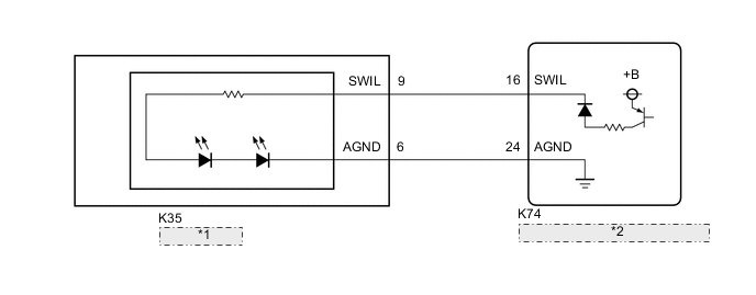
| *1 | Engine Switch |
| *2 | Certification ECU (Smart Key ECU Assembly) |
PROCEDURE
-
PERFORM ACTIVE TEST USING GTS (POWER/ENGINE SW LIGHT)
-
Connect the GTS to the DLC3.
-
Turn the engine switch on (IG).
-
Turn the GTS on.
-
Enter the following menus: Body Electrical / Entry and Start / Active Test.
-
Perform the Active Test according to the display on the GTS.
Body Electrical > Entry&Start > Active TestTester Display Measurement Item Control Range Diagnostic Note Power/Engine SW Light Engine switch illumination OFF or ON -
Body Electrical > Entry&Start > Active TestTester Display Power/Engine SW Light OK Engine switch illumination comes on. Result Proceed to OK NG
OK 
PROCEED TO NEXT SUSPECTED AREA SHOWN IN PROBLEM SYMPTOMS TABLE Click here
NG 
-
-
INSPECT ENGINE SWITCH
-
Remove the engine switch.
-
Inspect the engine switch.
OK Engine switch illumination is normal. Result Proceed to OK NG
NG
REPLACE ENGINE SWITCH Click here
OK
-
-
CHECK HARNESS AND CONNECTOR (ENGINE SWITCH - CERTIFICATION ECU (SMART KEY ECU ASSEMBLY))
-
Disconnect the K74 certification ECU (smart key ECU assembly) connector.
-
Disconnect the K35 engine switch connector.
-
Measure the resistance according to the value(s) in the table below.
Standard Resistance Tester Connection Condition Specified Condition K35-9 (SWIL) - K74-16 (SWIL) Always Below 1 Ω K35-6 (AGND) - K74-24 (AGND) Always Below 1 Ω K35-9 (SWIL) or K74-16 (SWIL) - Body ground Always 10 kΩ or higher K35-6 (AGND) or K74-24 (AGND) - Body ground Always 10 kΩ or higher Result Proceed to OK NG
OK
REPLACE CERTIFICATION ECU (SMART KEY ECU ASSEMBLY)
NG
REPAIR OR REPLACE HARNESS OR CONNECTOR
-