LIGHTING SYSTEM Door Courtesy Light Circuit
DESCRIPTION
The main body ECU (multiplex network body ECU) controls the front courtesy lights.
WIRING DIAGRAM

CAUTION / NOTICE / HINT
Note
First perform the communication function inspections in How to Proceed with Troubleshooting to confirm that there are no CAN communication malfunctions before troubleshooting this symptom.
PROCEDURE
-
PERFORM ACTIVE TEST USING GTS (COURTESY LIGHT)
-
Connect the GTS to the DLC3.
-
Turn the engine switch on (IG).
-
Turn the GTS on.
-
Enter the following menus: Body Electrical / Front Left Door / Active Test.
-
Enter the following menus: Body Electrical / Front Right Door / Active Test.
-
Perform the Active Test according to the display on the GTS.
Body Electrical > Front Left Door > Active TestTester Display Measurement Item Control Range Diagnostic Note Courtesy Light Front door courtesy light LH ON/OFF -
Body Electrical > Front Right Door > Active TestTester Display Measurement Item Control Range Diagnostic Note Courtesy Light Front door courtesy light RH ON/OFF -
Body Electrical > Front Left Door > Active TestTester Display Courtesy Light
Body Electrical > Front Right Door > Active TestTester Display Courtesy Light OK Front courtesy light comes on. Result Result Proceed to OK A NG (Front courtesy light RH does not illuminates) B NG (Front courtesy light LH does not illuminates) C
A 
PROCEED TO NEXT SUSPECTED AREA SHOWN IN PROBLEM SYMPTOMS TABLE Click here
C 
CHECK HARNESS AND CONNECTOR (FRONT COURTESY LIGHT LH - FRONT MULTIPLEX NETWORK DOOR ECU LH AND BATTERY) Click here
B 
-
-
CHECK HARNESS AND CONNECTOR (FRONT COURTESY LIGHT RH - FRONT MULTIPLEX NETWORK DOOR ECU RH AND BATTERY)
-
Disconnect the N24 front multiplex network door ECU RH.
-
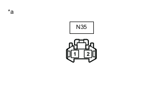
*a Front view of wire harness connector
(to Front Courtesy Light RH)
Disconnect the front courtesy light RH connector.
-
Measure the voltage according to the value(s) in the table below.
Standard Voltage Tester Connection Condition Specified Condition N35-1 - Body ground Battery saving control not operating 11 to 14 V -
Measure the resistance according to the value(s) in the table below.
Standard Resistance Tester Connection Condition Specified Condition N35-2 - N24-13 (CYL) Always Below 1 Ω N35-2 or N24-13 (CYL) - Body ground Always 10 kΩ or higher Result Proceed to OK NG
NG
REPAIR OR REPLACE HARNESS OR CONNECTOR
OK
-
-
INSPECT FRONT COURTESY LIGHT RH
-
Remove the front courtesy light RH.
-
Inspect the front courtesy light RH.
Result Proceed to OK NG
OK
REPLACE FRONT MULTIPLEX NETWORK DOOR ECU RH Click here
NG
REPLACE FRONT COURTESY LIGHT RH Click here
-
-
CHECK HARNESS AND CONNECTOR (FRONT COURTESY LIGHT LH - FRONT MULTIPLEX NETWORK DOOR ECU LH AND BATTERY)
-
Disconnect the O4 front multiplex network door ECU LH connector.
-
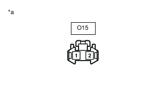
*a Front view of wire harness connector
(to Front Courtesy Light LH)
Disconnect the front courtesy light LH connector.
-
Measure the voltage according to the value(s) in the table below.
Standard Voltage Tester Connection Condition Specified Condition O15-1 - Body ground Battery saving control not operating 11 to 14 V -
Measure the resistance according to the value(s) in the table below.
Standard Resistance Tester Connection Condition Specified Condition O15-2 - O4-13 (CYL) Always Below 1 Ω O15-2 or O4-13 (CYL)- Body ground Always 10 kΩ or higher Result Proceed to OK NG
NG
REPAIR OR REPLACE HARNESS OR CONNECTOR
OK
-
-
INSPECT FRONT COURTESY LIGHT LH
-
Remove the front courtesy light LH.
-
Inspect the front courtesy light LH.
Result Proceed to OK NG
OK
REPLACE FRONT MULTIPLEX NETWORK DOOR ECU LH Click here
NG
REPLACE FRONT COURTESY LIGHT LH Click here
-