LIGHTING SYSTEM TERMINALS OF ECU
-
CHECK COWL SIDE JUNCTION BLOCK LH, MAIN BODY ECU (MULTIPLEX NETWORK BODY ECU)
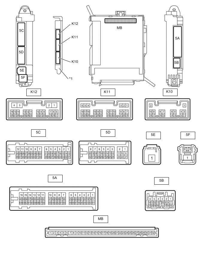
*1 Main Body ECU (Multiplex Network Body ECU) - -
-
Remove the main body ECU (multiplex network body ECU) from the cowl side junction block LH.
-
Connect the cowl side junction block LH connectors.
-
Measure the voltage and resistance according to the value(s) in the table below.
Terminal No. (Symbol) Wiring Color Terminal Description Condition Specified Condition MB-32 (IG) - Body ground - Ignition power supply Engine switch on (IG) 11 to 14 V MB-30 (BECU) - Body ground - Battery power supply Always 11 to 14 V MB-29 (ACC) - Body ground - ACC power supply Engine switch on (ACC) 11 to 14 V MB-11 (GND1) - Body ground - Ground Always Below 1 Ω If the result is not as specified, there may be a malfunction in the wire harness or passenger side junction block.
-
Install the main body ECU (multiplex network body ECU).
-
Measure the voltage and pulse according to the value(s) in the table below.
Terminal No. (Symbol) Wiring Color Terminal Description Condition Specified Condition K12-1 (RCYL) - Body ground GR - Body ground Rear courtesy light RH signal Rear courtesy light RH off 11 to 14 V Rear courtesy light RH on Below 1 V K12-2 (LSWR) - Body ground B - Body ground Rear door unlock detection switch RH signal Front door RH unlocked Below 1 V Engine switch off, all doors closed and rear door RH locked 11 to 14 V K12-20 (FSPT) - Body ground B - Body ground Interior foot light and door illumination signal Rear door inside handle illumination light, No. 1 interior illumination light (rear door ambient light) and front interior foot lights off 11 to 14 V Rear door inside handle illumination light, No. 1 interior illumination light (rear door ambient light) and front interior foot lights on Below 1 V K11-6 (RCTY) - Body ground G - Body ground Rear door courtesy light switch RH signal Rear door RH open Below 1 V Rear door RH closed Pulse generation K11-7 (LSFL) - Body ground SB - Body ground Front door unlock detection switch LH signal Front door LH unlocked Below 1 V Engine switch off, all doors closed and front door LH locked Pulse generation K11-18 (LSFR) - Body ground SB - Body ground Front door unlock detection switch RH signal Front door RH unlocked Below 1 V Engine switch off, all doors closed and front door RH locked Pulse generation K10-2 (DOMR) - Body ground Y - Body ground Battery saving control signal Battery saving control for map light, spot light and vanity light operating 11 to 14 V Battery saving control for map light, spot light and vanity light not operating Below 1 V K10-3 (LCTY) - Body ground G - Body ground Rear door courtesy light switch LH signal Rear door LH open Below 1 V Rear door LH closed Pulse generation K10-4 (LCYL) - Body ground GR - Body ground Rear courtesy light LH signal Rear courtesy light LH off 11 to 14 V Rear courtesy light LH on Below 1 V K10-5 (PANL) - Body ground V - Body ground Instrument panel illumination signal Headlight dimmer switch in TAIL Below 1 V Headlight dimmer switch off 11 to 14 V 5A-27 (ILE) - Body ground SB - Body ground Map light and spot light signal Map light and spot light on using illuminated entry system Below 1 V Map light and spot light off using illuminated entry system 11 to 14 V 5A-33 (FRCY) - Body ground R - Body ground Front door courtesy light switch RH signal Front door RH open Below 1 V Front door RH closed Pulse generation 5A-4 - Body ground L - Body ground Battery saving control signal Battery saving control operating Below 1 V Battery saving control not operating 11 to 14 V 5A-8 - Body ground B - Body ground Battery saving control signal Battery saving control operating Below 1 V Battery saving control not operating 11 to 14 V 5A-9 - Body ground L - Body ground Battery saving control signal Battery saving control operating Below 1 V Battery saving control not operating 11 to 14 V 5A-22 - Body ground G - Body ground Battery saving control signal Battery saving control operating Below 1 V Battery saving control not operating 11 to 14 V 5A-30 - Body ground L - Body ground Battery saving control signal Battery saving control operating Below 1 V Battery saving control not operating 11 to 14 V 5C-30 (LSWL) - Body ground B - Body ground Rear door unlock detection switch LH signal Rear door LH unlocked Below 1 V Engine switch off, all doors closed and rear door LH locked Pulse generation 5C-44 (FLCY) - Body ground R - Body ground Front door courtesy light switch LH signal Front door LH open Below 1 V Front door LH closed Pulse generation 5C-38 - Body ground Y - Body ground Battery saving control signal Battery saving control operating Below 1 V Battery saving control not operating 11 to 14 V 5C-39 - Body ground L - Body ground Battery saving control signal Battery saving control operating Below 1 V Battery saving control not operating 11 to 14 V 5C-42 - Body ground GR - Body ground Battery saving control signal Battery saving control operating Below 1 V Battery saving control not operating 11 to 14 V
-
-
CHECK FRONT MULTIPLEX NETWORK DOOR ECU RH

-
Disconnect the N24 front multiplex network door ECU RH connector.
-
Measure the resistance and voltage according to the value(s) in the table below.
Terminal No. (Symbol) Wiring Color Terminal Description Condition Specified Condition N24-6 (BDR) - Body ground V - Body ground Battery power supply Always 11 to 14 V N24-4 (CPUB) - Body ground P - Body ground Battery power supply Always 11 to 14 V N24-3 (SIG) - Body ground B - Body ground Ignition power supply Engine switch on (IG) 11 to 14 V N24-1 (GND) - Body ground W-B - Body ground Ground Always Below 1 Ω If the result is not as specified, there may be a malfunction on the wire harness side.
-
Reconnect the N24 front multiplex network door ECU RH connector.
-
Measure the voltage according to the value(s) in the table below.
Terminal No. (Symbol) Wiring Color Terminal Description Condition Specified Condition N24-10 (LED+) - N24-11 (LED-) Y - W Front door inside handle illumination light RH signal Front door inside handle illumination light RH on 11 to 14 V Front door inside handle illumination light RH off Below 1 V N24-12 (IL1+) - N3-21 (IL1-) P - SB No. 1 interior illumination light RH (front door ambient light) signal No. 1 interior illumination light RH (front door ambient light) on 11 to 14 V No. 1 interior illumination light RH (front door ambient light) off Below 1 V N24-13 (CYL) - Body ground GR - Body ground Front courtesy light RH signal Front courtesy light RH on Below 1 V Front courtesy light RH off 11 to 14 V z11-2 (MLP) - z11-12 (-) Y - B-R Door mirror foot light RH signal Door mirror foot light RH on 11 to 14 V Door mirror foot light RH off Below 1 V
-
-
CHECK FRONT MULTIPLEX NETWORK DOOR ECU LH

-
Disconnect the O4 front multiplex network door ECU LH connector.
-
Measure the resistance and voltage according to the value(s) in the table below.
Terminal No. (Symbol) Wiring Color Terminal Description Condition Specified Condition O4-6 (BDR) - Body ground V - Body ground Battery power supply Always 11 to 14 V O4-4 (CPUB) - Body ground P - Body ground Battery power supply Always 11 to 14 V O4-16 (BCUT) - Body ground L - Body ground Battery power supply Always 11 to 14 V O4-3 (SIG) - Body ground B - Body ground Ignition power supply Engine switch on (IG) 11 to 14 V O4-1 (GND) - Body ground W-B - Body ground Ground Always Below 1 Ω If the result is not as specified, there may be a malfunction on the wire harness side.
-
Reconnect the O4 front multiplex network door ECU LH connector.
-
Measure the voltage according to the value(s) in the table below.
Terminal No. (Symbol) Wiring Color Terminal Description Condition Specified Condition O4-10 (LED+) - O4-11 (LED-) Y - W Front door inside handle illumination light LH signal Front door inside handle illumination light LH on 11 to 14 V Front door inside handle illumination light LH off Below 1 V O4-12 (IL1+) - O3-21 (IL1-) P - SB No. 1 interior illumination light LH (front door ambient light) signal No. 1 interior illumination light LH (front door ambient light) on 11 to 14 V No. 1 interior illumination light LH (front door ambient light) off Below 1 V O4-13 (CYL) - Body ground GR - Body ground Front courtesy light LH signal Front courtesy light LH on Below 1 V Front courtesy light LH off 11 to 14 V z10-2 (MLP) - z10-12 (-) Y - B-R Door mirror foot light LH signal Door mirror foot light LH on 11 to 14 V Door mirror foot light LH off Below 1 V
-
-
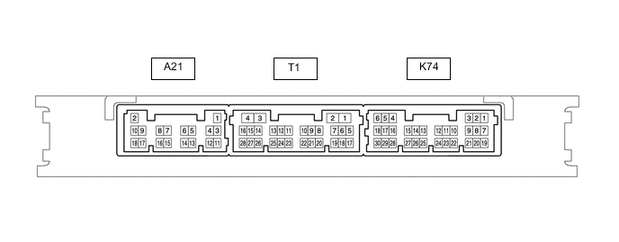
CHECK CERTIFICATION ECU (SMART KEY ECU ASSEMBLY)
-
Disconnect the A21 and K74 certification ECU connectors.
-
Measure the resistance and voltage according to the value(s) in the table below.
Terminal No. (Symbol) Wiring Color Terminal Description Condition Specified Condition A21-2 (+B) - Body ground W - Body ground Battery power supply Always 11 to 14 V A21-10 (CUTB) - Body ground P - Body ground*1
B - Body ground*2
Battery power supply Always 11 to 14 V K74-5 (IG) - Body ground B - Body ground Ignition power supply Engine switch on (IG) 11 to 14 V A21-11 (E) - Body ground W-B - Body ground Ground Always Below 1 Ω
-
*1: for LHD
-
*2: for RHD
If the result is not as specified, there may be a malfunction on the wire harness side.
-
-
Reconnect the A21 and K74 certification ECU connectors.
-
Measure the voltage according to the value(s) in the table below.
Terminal No. (Symbol) Wiring Color Terminal Description Condition Specified Condition K74-16 (SWIL) - Body ground B - Body ground Engine switch illumination operation signal Engine switch illumination on 11 to 14 V Engine switch illumination off Below 1 V
-