ENTRY AND START SYSTEM(for Start Function) Engine does not Start
DESCRIPTION
When the key is in the vehicle and the engine switch is pressed, the certification ECU (smart key ECU assembly) receives a signal and changes the power source mode. In addition, when the shift lever is in P or N and the brake pedal is depressed, the engine can be started by pressing the engine switch.
Tech Tips
-
When the certification ECU (smart key ECU assembly) is replaced with a new one and the cable is connected to the negative (-) battery terminal, the power source mode changes to on (IG).
-
When the battery cable is disconnected and reconnected, the power source returns to the mode it was in before the battery cable was disconnected.
| Problem Symptom | Data List Item | Active Test Item |
|---|---|---|
| Engine does not start |
Power Source Control:
Entry&Start:
Starting Control: |
- |
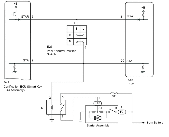
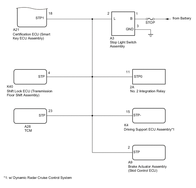
WIRING DIAGRAM
CAUTION / NOTICE / HINT
Note
-
When using the GTS with the engine switch off, connect the GTS to the DLC3 and turn a courtesy light switch on and off at intervals of 1.5 seconds or less until communication between the GTS and the vehicle begins. Then select Model Code "KEY REGIST" under manual mode and enter the following menus: Body Electrical / Entry&Start(CAN). While using the GTS, periodically turn a courtesy light switch on and off at intervals of 1.5 seconds or less to maintain communication between the GTS and the vehicle.
-
The entry and start system (for Start Function) uses a multiplex communication system (LIN communication system) and the CAN communication system. Inspect the communication function by following How to Proceed with Troubleshooting Click here. Troubleshoot the entry and start system (for Start Function) after confirming that the communication systems are functioning properly.
-
If the entry and start system is disabled through the customize function, enable the system before performing troubleshooting.
-
Before replacing the certification ECU (smart key ECU assembly), steering lock ECU (steering lock actuator or upr bracket assembly), ECM or ID code box (immobiliser code ECU), refer to the entry and start system (for Start Function) precaution.
-
Inspect the fuses of circuits related to this system before performing the following inspection procedure.
-
If the steering lock ECU (steering lock actuator or upr bracket assembly) is replaced, be sure to confirm that the steering is unlocked by turning the steering wheel to the left and right before starting the engine. If the steering is locked for any reason, open and close a door with the engine switch off, and then unlock the steering by pressing the engine switch. This prevents the engine from starting while the steering is locked.
-
After completing repairs, confirm that the problem does not occur.
Tech Tips
If the brake pedal is repeatedly depressed while the engine is stopped, the brake booster pressure is released and the force required to depress the brake pedal to illuminate the stop lights increases.
PROCEDURE
-
CHECK BATTERY
-
Measure the battery voltage.
Standard Voltage 11 to 14 V Tech Tips
-
It may be possible to tell whether the vehicle battery is discharged by operating the horn.
-
If the battery voltage is less than 11 V, charge or replace it.
Result Proceed to NEXT -
NEXT 
-
-
CHECK FOR DTC
-
Using the GTS, confirm the output of DTCs for all systems.
OK No DTCs are output. Note
Make sure that no DTCs are output. If any DTCs are output, proceed to the Diagnostic Trouble Code Chart.
Result Proceed to OK NG
NG 
GO TO DTC CHART
OK
-
-
CHECK WAVE ENVIRONMENT
-
If the problem occurs in certain locations or times of day, the possibility of wave interference is high.
Tech Tips
Whether or not the problem is due to wave interference can be checked by holding the electrical key transmitter sub-assembly near the door control receiver (RF band).
OK Engine starts. Result Proceed to OK NG
OK
AFFECTED BY WAVE INTERFERENCE
NG
-
-
CHECK ENGINE SWITCH CONDITION
-
Get into the vehicle while carrying an electrical key transmitter sub-assembly.
-
Move the shift lever to P.
-
With the brake pedal released, check that pressing the engine switch causes the power source mode to change.
Result Result Proceed to Off → on (ACC) → on (IG) → off A Power source mode does not change to on (ACC) and on (IG) B Power source mode changes to on (ACC) but not to on (IG) C Power source mode changes to on (IG) but not to on (ACC) D
B
GO TO POWER SOURCE MODE DOES NOT CHANGE TO ON (IG AND ACC) Click here
C
GO TO POWER SOURCE MODE DOES NOT CHANGE TO ON (IG) Click here
D
GO TO POWER SOURCE MODE DOES NOT CHANGE TO ON (ACC) Click here
A
-
-
CHECK CRANKING FUNCTION
-
Get into the vehicle while carrying an electrical key transmitter sub-assembly.
-
Move the shift lever to P.
-
Depress the brake pedal.
-
Confirm that the entry warning light is displayed, and then press the engine switch and check that the engine cranks.
OK Engine cranks. Result Result Proceed to OK A NG (w/ Canister Pump Module) B NG (w/o Canister Pump Module) C
B
GO TO SFI SYSTEM (PROBLEM SYMPTOMS TABLE) Click here
C
GO TO SFI SYSTEM (PROBLEM SYMPTOMS TABLE) Click here
A
-
-
CHECK SECURITY INDICATOR LIGHT (ENGINE IMMOBILISER SYSTEM UNSET)
-
Get into the vehicle while carrying an electrical key transmitter sub-assembly.
-
Move the shift lever to P.
-
Press the engine switch with the brake pedal released and check that the security indicator light changes from blinking to off at the same time that the power source mode changes to on (ACC).
Tech Tips
It is determined that the engine immobiliser function is operating correctly if the security indicator light changes from blinking to off at the same time that the power source mode changes to on (ACC).
OK Security indicator light changes from blinking to off at the same time that the power source mode changes to on (ACC). Result Proceed to OK NG
NG 
READ VALUE USING GTS (S CODE CHECK) Click here
OK
-
-
CHECK COMBINATION METER ASSEMBLY
-
Get into the vehicle while carrying the key, move the shift lever to P, press the engine switch while depressing the brake pedal and check that the combination meter indicator changes.
Tech Tips
If the entry warning light is displayed when the procedure above is performed, the P, N and brake signals can be considered to be normal.
OK The entry warning light is displayed. Result Proceed to OK NG
NG
READ VALUE USING GTS (NEUTRAL SW/ CLUTCH SW, SHIFT POSITION P OR N) Click here
OK
-
-
READ VALUE USING GTS (STARTER SW)
-
Connect the GTS to the DLC3.
-
Turn the engine switch on (IG).
-
Turn the GTS on.
-
Enter the following menus: Body Electrical / Starting Control / Data List.
-
Get into the vehicle while carrying the electrical key transmitter sub-assembly, move the shift lever to P, press the engine switch while depressing the brake pedal and confirm that the Data List item changes.
Body Electrical > Starting Control > Data ListTester Display Measurement Item Range Normal Condition Diagnostic Note Starter SW Starter operation request ON or OFF ON: Starter operation requested
OFF: Starter operation not requested
When malfunctioning, the engine will not crank
Body Electrical > Starting Control > Data ListTester Display Starter SW OK The Data List item changes. Result Proceed to OK NG
NG
REPLACE CERTIFICATION ECU (SMART KEY ECU ASSEMBLY)
OK
-
-
INSPECT ST RELAY (STARTER RELAY ASSEMBLY)
-
Remove the ST relay (starter relay assembly) from the No. 1 engine room relay block.
-
Inspect the ST relay (starter relay assembly).
Result Proceed to OK NG
NG
REPLACE ST RELAY (STARTER RELAY ASSEMBLY)
OK
-
-
CHECK HARNESS AND CONNECTOR (CERTIFICATION ECU (SMART KEY ECU ASSEMBLY) - BODY GROUND)
-
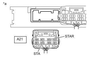
*a Rear view of wire harness connector
(to Certification ECU (Smart Key ECU Assembly))
Disconnect the certification ECU (smart key ECU assembly) connector.
-
Move the shift lever to P or N.
-
Measure the resistance according to the value(s) in the table below.
Standard Resistance Tester Connection Condition Specified Condition A21-5 (STAR) - Body ground 20°C (68°F) 100 to 150 Ω A21-7 (STA) - Body ground Result Proceed to OK NG
NG
REPAIR OR REPLACE HARNESS OR CONNECTOR
OK
-
-
INSPECT STARTER ASSEMBLY
-
Remove the starter assembly.
-
Inspect the starter assembly.
Result Proceed to OK NG
NG
REPLACE STARTER ASSEMBLY Click here
OK
-
-
CHECK HARNESS AND CONNECTOR (BATTERY - STARTER AND ST RELAY (STARTER RELAY ASSEMBLY))
-
Remove the starter assembly from the vehicle to perform an inspection.
-
Remove the ST relay (starter relay assembly) from the No. 1 engine room relay block.
-
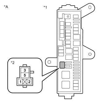
*A for LHD *1 No. 1 Engine Room Relay Block *2 ST Relay (Starter Relay Assembly) Holder 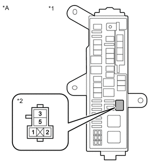
*A for RHD *1 No. 1 Engine Room Relay Block *2 ST Relay (Starter Relay Assembly) Holder Measure the voltage according to the value(s) in the table below.
Standard Voltage Tester Connection Condition Specified Condition F2-1 - Body ground Always 11 to 14 V 5 (ST relay (starter relay assembly)) - Body ground -
Measure the resistance according to the value(s) in the table below.
Standard Resistance Tester Connection Condition Specified Condition 3 (ST relay (starter relay assembly)) - E43-1 Always Below 1 Ω 3 (ST relay (starter relay assembly)) or E43-1 - Body ground 10 kΩ or higher Result Proceed to OK NG
OK
REPLACE CERTIFICATION ECU (SMART KEY ECU ASSEMBLY)
NG
REPAIR OR REPLACE HARNESS OR CONNECTOR
-
-
READ VALUE USING GTS (NEUTRAL SW/ CLUTCH SW, SHIFT POSITION P OR N)
-
Connect the GTS to the DLC3.
-
Turn the engine switch on (IG).
-
Turn the GTS on.
-
Enter the following menus: Body Electrical / Power Source Control and Starting Control / Data List.
-
According to the display on the GTS, read the Data List.
Body Electrical > Power Source Control > Data ListTester Display Measurement Item Range Normal Condition Diagnostic Note Neutral SW/ Clutch SW Shift position (P, N) ON or OFF ON: Shift lever in P or N
OFF: Shift lever not in P or N
-
Use this item to determine whether the park/neutral position switch is malfunctioning.
-
When the engine cannot be started due to a park/neutral position switch malfunction, OFF is displayed.
Body Electrical > Power Source Control > Data ListTester Display Neutral SW/ Clutch SW
Body Electrical > Starting Control > Data ListTester Display Measurement Item Range Normal Condition Diagnostic Note Shift Position P or N Condition of park/neutral position switch ON or OFF ON: Shift lever in P or N
OFF: Shift lever not in P or N
When malfunctioning, the engine will not crank.
Body Electrical > Starting Control > Data ListTester Display Shift Position P or N OK The item in the Data List changes according to the shift position. Result Proceed to OK NG -
NG
INSPECT PARK/NEUTRAL POSITION SWITCH Click here
OK
-
-
READ VALUE USING GTS (STOP LIGHT SWITCH1)
-
Connect the GTS to the DLC3.
-
Turn the engine switch on (IG).
-
Turn the GTS on.
-
Enter the following menus: Body Electrical / Power Source Control / Data List.
-
According to the display on the GTS, read the Data List.
Body Electrical > Power Source Control > Data ListTester Display Measurement Item Range Normal Condition Diagnostic Note Stop Light Switch1 State of brake pedal ON or OFF ON: Brake pedal depressed
OFF: Brake pedal released
-
Use this item to determine whether the stop light switch is malfunctioning.
-
The engine cannot be started when this item is OFF.
-
When this item is malfunctioning, the engine can be started by pressing and holding the engine switch for a certain period of time.
Body Electrical > Power Source Control > Data ListTester Display Stop Light Switch1 OK The item in the Data List changes when the brake pedal is depressed and released. Result Proceed to OK NG -
OK
REPLACE CERTIFICATION ECU (SMART KEY ECU ASSEMBLY)
NG
-
-
CHECK HARNESS AND CONNECTOR (CERTIFICATION ECU (SMART KEY ECU ASSEMBLY) - STOP LIGHT SWITCH ASSEMBLY)
-
Disconnect the A3 stop light switch assembly connector.
-
Disconnect the A21 certification ECU (smart key ECU assembly) connector.
-
Disconnect the K40 shift lock ECU (transmission floor shift assembly) connector.
-
Disconnect the A28 TCM connector.
-
Disconnect the K4 driving support ECU assembly connector.*1
-
*1: Dynamic Radar cruise Control System
-
-
Disconnect the A9 skid control ECU (brake actuator assembly) connector.
-
Disconnect the 2A No. 2 integration relay connector.
-
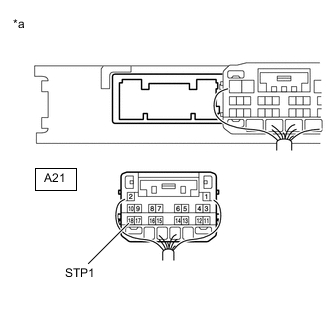
*a Rear view of wire harness connector
(to Certification ECU (Smart Key ECU Assembly))
Measure the resistance according to the value(s) in the table below.
Standard Resistance Tester Connection Condition Specified Condition A21-18 (STP1) - A3-2 (L) Always Below 1 Ω A3-3 (GND) - Body ground Below 1 Ω A21-18 (STP1) or A3-2 (L) - Body ground 10 kΩ or higher -
Reconnect the A3 stop light switch assembly connector.
-
Measure the voltage according to the valve(s) in the table below.
Standard Voltage Tester Connection Condition Specified Condition A21-18 (STP1) - Body ground Brake pedal released 1 V or less Brake pedal depressed 9 V or higher Result Proceed to OK NG
NG
REPAIR OR REPLACE HARNESS AND CONNECTOR
OK
-
-
INSPECT STOP LIGHT SWITCH ASSEMBLY
-
Remove the stop light switch assembly.
-
Inspect the stop light switch assembly.
Result Proceed to OK NG
OK
REPLACE CERTIFICATION ECU (SMART KEY ECU ASSEMBLY)
NG
REPLACE STOP LIGHT SWITCH ASSEMBLY Click here
-
-
INSPECT PARK/NEUTRAL POSITION SWITCH
-
Remove the park/neutral position switch.
-
Inspect the park/neutral position switch.
Result Proceed to OK NG
NG
REPLACE PARK/NEUTRAL POSITION SWITCH Click here
OK
-
-
CHECK HARNESS AND CONNECTOR (CERTIFICATION ECU (SMART KEY ECU ASSEMBLY) - PARK/NEUTRAL POSITION SWITCH)
-
Disconnect the A21 certification ECU (smart key ECU assembly) connector.
-
Disconnect the E25 park/neutral position switch connector.
-
Measure the resistance according to the value(s) in the table below.
Standard Resistance Tester Connection Condition Specified Condition A21-5 (STAR) - E25-4 (B) Always Below 1 Ω A21-5 (STAR) or E25-4 (B) - Body ground Always 10 kΩ or higher -
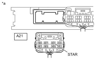
*a Rear view of wire harness connector
(to Certification ECU (Smart Key ECU Assembly))
Reconnect the E25 park/neutral position switch connector.
-
Measure the voltage according to the value(s) in the table below.
Standard Voltage Tester Connection Switch Condition Specified Condition A21-5 (STAR) - Body ground Engine switch pressed and held with brake pedal depressed (starter on) → Engine switch released after approximately 1 second elapses (starter off) 6 V or higher* → 1.5 V or less Tech Tips
*: When the engine is cranking, the battery voltage may momentarily drop to approximately 6 V.
Result Proceed to OK NG
OK
REPLACE CERTIFICATION ECU (SMART KEY ECU ASSEMBLY)
NG
REPAIR OR REPLACE HARNESS AND CONNECTOR
-
-
READ VALUE USING GTS (S CODE CHECK)
-
Connect the GTS to the DLC3.
-
Turn the engine switch on (IG).
-
Turn the GTS on.
-
Enter the following menus: Body Electrical / Entry&Start / Data List.
-
According to the display on the GTS, read the Data List.
Body Electrical > Entry&Start > Data ListTester Display Measurement Item Range Normal Condition Diagnostic Note S Code Check Verification result between certification ECU (smart key ECU assembly) and ID code box (immobiliser code ECU) OK or NG OK: Verification result normal
NG: Verification result abnormal
When NG is displayed:
-
The ID code for the certification ECU (smart key ECU assembly) or ID code box (immobiliser code ECU) is not registered or the certification ECU (smart key ECU assembly) or ID code box (immobiliser code ECU) is malfunctioning.
-
The steering cannot be locked.
-
The steering cannot be unlocked (the engine cannot be started).
Body Electrical > Entry&Start > Data ListTester Display S Code Check Tech Tips
-
The certification ECU (smart key ECU assembly) or the ID code box (immobiliser code ECU) is malfunctioning.
-
There is a problem with the communication between ECUs.
-
An ECU is replaced, but is not registered.
-
An ECU is replaced with an ECU which has a code already stored in it.
Reasons for verification failure:
OK OK (S code certification result normal) appears on the screen. Result Proceed to OK NG -
NG
REPLACE CERTIFICATION ECU (SMART KEY ECU ASSEMBLY) Click here
OK
-
-
CHECK STEERING LOCK
-
Check that the steering unlocks when the engine switch is turned on (ACC).
OK The steering unlocks. Result Proceed to OK NG
NG
READ VALUE USING GTS (STEERING UNLOCK SWITCH) Click here
OK
-
-
READ VALUE USING GTS (IMMOBILISER)
-
Connect the GTS to the DLC3.
-
Turn the engine switch on (IG).
-
Turn the GTS on.
-
Enter the following menus: Body Electrical / Entry&Start / Data List.
-
According to the display on the GTS, read the Data List.
Body Electrical > Entry&Start > Data ListTester Display Measurement Item Range Normal Condition Diagnostic Note Immobiliser Engine immobiliser system determined by certification ECU (smart key ECU assembly) Set or Unset Set: Engine immobiliser system set (engine start prohibited) (engine switch off)
Unset: Engine immobiliser system unset (engine start permitted) (engine switch on(ACC) or on (IG))
The engine cannot be started when Set is displayed.
Tech Tips
-
The security indicator light blinks when Set is displayed.
-
The security indicator light is linked with set/unset of the immobiliser and not linked with steering lock/unlock.
Body Electrical > Entry&Start > Data ListTester Display Immobiliser OK The Data List item changes to "Unset" when the engine switch is turned on (ACC) or on (IG). Result Proceed to OK NG -
NG
GO TO STEP 25 Click here
OK
-
-
READ VALUE USING GTS (STARTER REQUEST SIGNAL)
-
Connect the GTS to the DLC3.
-
Turn the engine switch on (IG).
-
Turn the GTS on.
-
Enter the following menus: Body Electrical / Power Source Control / Data List.
-
According to the display on the GTS, read the Data List.
Body Electrical > Power Source Control > Data ListTester Display Measurement Item Range Normal Condition Diagnostic Note Starter Request Signal Engine start request signal status ON or OFF
-
ON: With the shift lever in P and brake pedal depressed, the engine switch is pressed and held
OFF: After approximately 1 second has elapsed, the engine switch is released
except Manual Transaxle
-
ON: With the clutch pedal depressed, the engine switch is pressed and held
OFF: After approximately 1 second has elapsed, the engine switch is released
for Manual Transaxle
-
When the engine cannot be started due to a start request signal malfunction, OFF is displayed.
-
When the engine switch is pressed, the duration of time that ON is displayed will be extremely short. As such, the engine switch needs to be pressed and held for a certain amount of time.
Body Electrical > Power Source Control > Data ListTester Display Starter Request Signal Note
Check that the entry warning is displayed on the multi-information display on the combination meter assembly, and then press the engine switch.
OK The display changes in response to the operation of the engine switch. Result Proceed to OK NG -
OK
USE SIMULATION METHOD TO CHECK Click here
NG
GO TO STEP 27 Click here
-
-
READ VALUE USING GTS (STEERING UNLOCK SWITCH)
-
Connect the GTS to the DLC3.
-
Turn the engine switch on (IG).
-
Turn the GTS on.
-
Enter the following menus: Body Electrical / Power Source Control / Data List.
-
According to the display on the GTS, read the Data List.
Body Electrical > Power Source Control > Data ListTester Display Measurement Item Range Normal Condition Diagnostic Note Steering Unlock Switch State of steering unlock sensor signal output from steering lock actuator assembly ON or OFF ON: Steering unlocked
OFF: Steering locked
-
When the shift lever is in P and the engine switch is off, if any door is opened or closed, the steering is locked.
-
When the key is inside the vehicle and the engine switch is turned on (ACC) or on (IG), the steering unlocks.
-
The engine cannot be started when the steering unlock signal is off.
Body Electrical > Power Source Control > Data ListTester Display Steering Unlock Switch OK The item in the Data List indicates "ON" (the steering is unlocked). Result Proceed to OK NG -
OK
GO TO STEERING LOCK SYSTEM (UNABLE TO UNLOCK STEERING WHEEL) Click here
NG
-
-
READ VALUE USING GTS (L CODE CHECK)
-
Connect the GTS to the DLC3.
-
Turn the engine switch on (IG).
-
Turn the GTS on.
-
Enter the following menus: Body Electrical / Entry&Start / Data List.
-
According to the display on the GTS, read the Data List.
Body Electrical > Entry&Start > Data ListTester Display Measurement Item Range Normal Condition Diagnostic Note L Code Check Verification result between ID code box (immobiliser code ECU) and steering lock ECU (steering lock actuator or upr bracket assembly) OK or NG OK: Verification result normal
NG: Verification result abnormal
When NG is displayed:
-
The ID code for the ID code box (immobiliser code ECU) or steering lock ECU (steering lock actuator or upr bracket assembly) is not registered or the certification ECU (smart key ECU assembly) or steering lock ECU (steering lock actuator or upr bracket assembly) is malfunctioning.
-
The steering cannot be locked.
-
The steering cannot be unlocked (the engine cannot be started).
Body Electrical > Entry&Start > Data ListTester Display L Code Check Tech Tips
-
The steering lock ECU (steering lock actuator or upr bracket assembly) or ID code box (immobiliser code ECU) is malfunctioning.
-
There is a problem with the communication between ECUs.
-
An ECU is replaced, but is not registered.
-
An ECU is replaced with an ECU which has a code already stored in it.
Reasons for verification failure:
OK The Data List item changes to "OK" when the key is inside the vehicle. Result Proceed to OK NG -
OK
REPLACE STEERING LOCK ECU (STEERING LOCK ACTUATOR OR UPR BRACKET ASSEMBLY) Click here
NG
READ VALUE USING GTS (S CODE CHECK) Click here
-
-
REPLACE CERTIFICATION ECU (SMART KEY ECU ASSEMBLY)
-
Replace the certification ECU (smart key ECU assembly) with a new one (Refer to the Service Bulletin).
-
Perform the registration procedures (Refer to the Service Bulletin).
-
Use the Data List to check if S code certification is functioning properly again.
Body Electrical > Entry&Start > Data ListTester Display Measurement Item Range Normal Condition Diagnostic Note S Code Check Verification result between certification ECU (smart key ECU assembly) and ID code box (immobiliser code ECU) OK or NG OK: Verification result normal
NG: Verification result abnormal
When NG is displayed:
-
The ID code for the certification ECU (smart key ECU assembly) or ID code box (immobiliser code ECU) is not registered or the certification ECU (smart key ECU assembly) or ID code box (immobiliser code ECU) is malfunctioning.
-
The steering cannot be locked.
-
The steering cannot be unlocked (the engine cannot be started).
Body Electrical > Entry&Start > Data ListTester Display S Code Check OK OK (S code certification result normal) appears on the screen. Result Proceed to OK NG -
OK
END
NG
REPLACE ID CODE BOX (IMMOBILISER CODE ECU) Click here
-
-
READ VALUE USING GTS (S CODE CHECK)
-
Replace the steering lock ECU (steering lock actuator or upr bracket assembly) with a new one.
-
Perform the registration procedures (Refer to the Service Bulletin).
-
Use the Data List to check if L code certification is functioning properly again.
Body Electrical > Entry&Start > Data ListTester Display Measurement Item Range Normal Condition Diagnostic Note L Code Check Verification result between ID code box (immobiliser code ECU) and steering lock ECU (steering lock actuator or upr bracket assembly) OK or NG OK: Verification result normal
NG: Verification result abnormal
When NG is displayed:
-
The ID code for the ID code box (immobiliser code ECU) or steering lock ECU (steering lock actuator or upr bracket assembly) is not registered or the certification ECU (smart key ECU assembly) or steering lock ECU (steering lock actuator or upr bracket assembly) is malfunctioning.
-
The steering cannot be locked.
-
The steering cannot be unlocked (the engine cannot be started).
Body Electrical > Entry&Start > Data ListTester Display L Code Check OK OK (L code certification result normal) appears on the screen. Result Proceed to OK NG -
OK
END
NG
REPLACE ID CODE BOX (IMMOBILISER CODE ECU)
-
-
REPLACE ID CODE BOX (IMMOBILISER CODE ECU)
-
Replace the ID code box (immobiliser code ECU) with a new one (Refer to the Service Bulletin).
-
Perform the registration procedures (Refer to the Service Bulletin).
-
Use the Data List to check if S code certification is functioning properly again.
Body Electrical > Entry&Start > Data ListTester Display Measurement Item Range Normal Condition Diagnostic Note S Code Check Verification result between certification ECU (smart key ECU assembly) and ID code box (immobiliser code ECU) OK or NG OK: Verification result normal
NG: Verification result abnormal
When NG is displayed:
-
The ID code for the certification ECU (smart key ECU assembly) or ID code box (immobiliser code ECU) is not registered or the certification ECU (smart key ECU assembly) or ID code box (immobiliser code ECU) is malfunctioning.
-
The steering cannot be locked.
-
The steering cannot be unlocked (the engine cannot be started).
Body Electrical > Entry&Start > Data ListTester Display S Code Check OK OK (S code certification result normal) appears on the screen. Result Proceed to NEXT -
NEXT
END
-