POWER DOOR LOCK CONTROL SYSTEM All Doors LOCK/UNLOCK Functions do not Operate Via Door Control Switch
DESCRIPTION
- for LHD:
Operating the power window regulator switch assembly (door control switch) sends a manual door lock/unlock request signal via direct line to the front multiplex network door ECU RH, and afterwards the manual door lock/unlock request signal is sent via CAN communication to the main body ECU (multiplex network body ECU).
After the main body ECU (multiplex network body ECU) receives the door lock/unlock request signal, it operates the door lock/unlock motors to lock/unlock each door.
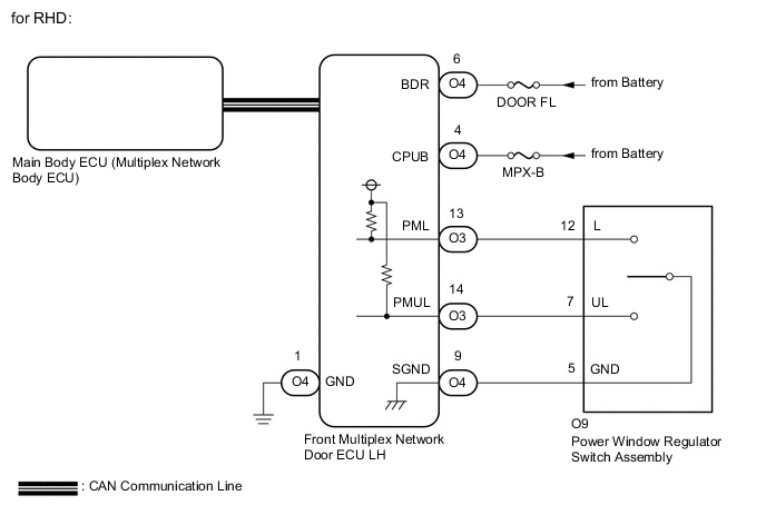
- for RHD:
Operating the power window regulator switch assembly (door control switch) sends a manual door lock/unlock request signal via direct line to the front multiplex network door ECU LH, and afterwards the manual door lock/unlock request signal is sent via CAN communication to the main body ECU (multiplex network body ECU).
After the main body ECU (multiplex network body ECU) receives the door lock/unlock request signal, it operates the door lock/unlock motors to lock/unlock each door.
WIRING DIAGRAM

CAUTION / NOTICE / HINT
Note
-
Inspect the fuses for circuits related to this system before performing the following inspection procedure.
-
The power door lock control system uses the CAN communication system. Inspect the communication function by following How to Proceed with Troubleshooting. Troubleshoot the power door lock control system after confirming that the communication systems are functioning properly.
-
If the main body ECU (multiplex network body ECU) is replaced, refer to Service Bulletin.
PROCEDURE
-
CONFIRM MODEL
-
Choose the model to be inspected.
Result Result Proceed to for LHD A for RHD B
B 
READ VALUE USING GTS (DOOR LOCK SW AND DOOR UNLOCK SW) Click here
A 
-
-
READ VALUE USING GTS (DOOR LOCK SW AND DOOR UNLOCK SW)
-
Connect the GTS to the DLC3.
-
Turn the engine switch on (IG).
-
Turn the GTS on.
-
Enter the following menus: Body Electrical / Front Right Door / Data List.
-
Read the Data List according to the display on the GTS.
Body Electrical > Front Right Door > Data ListTester Display Measurement Item Range Normal Condition Diagnostic Note Door Lock SW Power window regulator switch assembly (door control switch) lock signal OFF or ON ON: Lock side of power window regulator switch assembly pushed
OFF: Lock side of power window regulator switch assembly not pushed
- Door Unlock SW Power window regulator switch assembly (door control switch) unlock signal OFF or ON ON: Unlock side of power window regulator switch assembly pushed
OFF: Unlock side of power window regulator switch assembly not pushed
-
Body Electrical > Front Right Door > Data ListTester Display Door Lock SW Door Unlock SW Result Proceed to OK NG
OK 
REPLACE FRONT MULTIPLEX NETWORK DOOR ECU RH Click here
NG
-
-
INSPECT POWER WINDOW REGULATOR SWITCH ASSEMBLY
-
Remove the power window regulator switch assembly.
-
Inspect the power window regulator switch assembly.
Result Proceed to OK NG
NG
REPLACE POWER WINDOW REGULATOR SWITCH ASSEMBLY Click here
OK
-
-
CHECK HARNESS AND CONNECTOR (POWER WINDOW REGULATOR SWITCH ASSEMBLY - FRONT MULTIPLEX NETWORK DOOR ECU RH)
-
Disconnect the N3 and N24 front multiplex network door ECU RH connectors.
-
Disconnect the N29 power window regulator switch assembly connector.
-
Measure the resistance according to the value(s) in the table below.
Standard Resistance Tester Connection Condition Specified Condition N3-13 (PML) - N29-12 (L) Always Below 1 Ω N3-14 (PMUL) - N29-7 (UL) Always Below 1 Ω N24-9 (SGND) - N29-5 (GND) Always Below 1 Ω N3-13 (PML) or N29-12 (L) - Body ground Always 10 kΩ or higher N3-14 (PMUL) or N29-7 (UL) - Body ground Always 10 kΩ or higher N24-9 (SGND) or N29-5 (GND) - Body ground Always 10 kΩ or higher Result Proceed to OK NG
NG
REPAIR OR REPLACE HARNESS OR CONNECTOR
OK
-
-
CHECK HARNESS AND CONNECTOR (FRONT MULTIPLEX NETWORK DOOR ECU RH - BATTERY AND BODY GROUND)
-
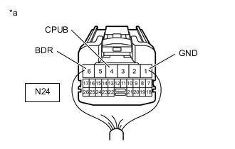
*a Rear view of wire harness connector
(to Front Multiplex Network Door ECU RH)
Disconnect the front multiplex network door ECU RH connector.
-
Measure the resistance according to the value(s) in the table below.
Standard Resistance Tester Connection Condition Specified Condition N24-1 (GND) - Body ground Always Below 1 Ω -
Measure the voltage according to the value(s) in the table below.
Standard Voltage Tester Connection Condition Specified Condition N24-4 (CPUB) - Body ground Always 11 to 14 V N24-6 (BDR) - Body ground Always 11 to 14 V Result Proceed to OK NG
OK
REPLACE FRONT MULTIPLEX NETWORK DOOR ECU RH Click here
NG
REPAIR OR REPLACE HARNESS OR CONNECTOR
-
-
READ VALUE USING GTS (DOOR LOCK SW AND DOOR UNLOCK SW)
-
Connect the GTS to the DLC3.
-
Turn the engine switch on (IG).
-
Turn the GTS on.
-
Enter the following menus: Body Electrical / Front Left Door / Data List.
-
Read the Data List according to the display on the GTS.
Body Electrical > Front Left Door > Data ListTester Display Measurement Item Range Normal Condition Diagnostic Note Door Lock SW Power window regulator switch assembly (door control switch) lock signal OFF or ON ON: Lock side of power window regulator switch assembly pushed
OFF: Lock side of power window regulator switch assembly not pushed
- Door Unlock SW Power window regulator switch assembly (door control switch) unlock signal OFF or ON ON: Unlock side of power window regulator switch assembly pushed
OFF: Unlock side of power window regulator switch assembly not pushed
-
Body Electrical > Front Left Door > Data ListTester Display Door Lock SW Door Unlock SW Result Proceed to OK NG
OK
REPLACE FRONT MULTIPLEX NETWORK DOOR ECU LH Click here
NG
-
-
INSPECT POWER WINDOW REGULATOR SWITCH ASSEMBLY
-
Remove the power window regulator switch assembly.
-
Inspect the power window regulator switch assembly.
Result Proceed to OK NG
NG
REPLACE POWER WINDOW REGULATOR SWITCH ASSEMBLY Click here
OK
-
-
CHECK HARNESS AND CONNECTOR (POWER WINDOW REGULATOR SWITCH ASSEMBLY - FRONT MULTIPLEX NETWORK DOOR ECU LH)
-
Disconnect the O3 and O4 front multiplex network door ECU LH connectors.
-
Disconnect the O9 power window regulator switch assembly connector.
-
Measure the resistance according to the value(s) in the table below.
Standard Resistance Tester Connection Condition Specified Condition O3-13 (PML) - O9-12 (L) Always Below 1 Ω O3-14 (PMUL) - O9-7 (UL) Always Below 1 Ω O4-9 (SGND) - O9-5 (GND) Always Below 1 Ω O3-13 (PML) or O9-12 (L) - Body ground Always 10 kΩ or higher O3-14 (PMUL) or O9-7 (UL) - Body ground Always 10 kΩ or higher O4-9 (SGND) or O9-5 (GND) - Body ground Always 10 kΩ or higher Result Proceed to OK NG
NG
REPAIR OR REPLACE HARNESS OR CONNECTOR
OK
-
-
CHECK HARNESS AND CONNECTOR (FRONT MULTIPLEX NETWORK DOOR ECU LH - BATTERY AND BODY GROUND)
-
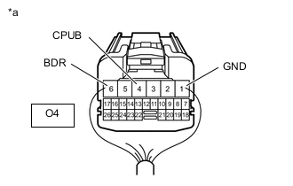
*a Rear view of wire harness connector
(to Front Multiplex Network Door ECU LH)
Disconnect the front multiplex network door ECU LH connector.
-
Measure the resistance according to the value(s) in the table below.
Standard Resistance Tester Connection Condition Specified Condition O4-1 (GND) - Body ground Always Below 1 Ω -
Measure the voltage according to the value(s) in the table below.
Standard Voltage Tester Connection Condition Specified Condition O4-4 (CPUB) - Body ground Always 11 to 14 V O4-6 (BDR) - Body ground Always 11 to 14 V Result Proceed to OK NG
OK
REPLACE FRONT MULTIPLEX NETWORK DOOR ECU LH Click here
NG
REPAIR OR REPLACE HARNESS OR CONNECTOR
-