POWER DOOR LOCK CONTROL SYSTEM All Doors LOCK/UNLOCK Functions do not Operate Via Door Control Switch or Door Key Cylinder
DESCRIPTION
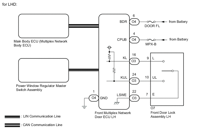
- for LHD:
Operating the power window regulator master switch assembly (door control switch) sends a manual door lock/unlock request signal via LIN communication to the front multiplex network door ECU LH, and afterwards the manual door lock/unlock request signal is sent via CAN communication to the main body ECU (multiplex network body ECU).
Driver door key-linked operation (front door lock assembly LH) sends a key-linked door lock/unlock request signal via direct line to the front multiplex network door ECU LH, and then via CAN communication to the main body ECU (multiplex network body ECU).
After the main body ECU (multiplex network body ECU) receives the door lock/unlock request signal, it operates the door lock/unlock motors to lock/unlock each door.
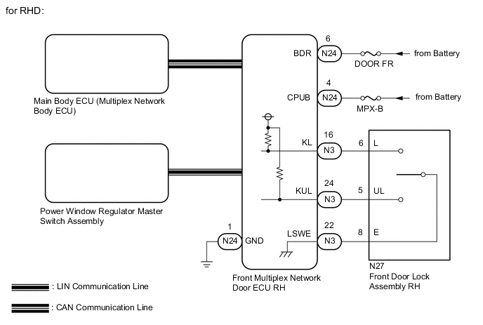
- for RHD:
Operating the power window regulator master switch assembly (door control switch) sends a manual door lock/unlock request signal via LIN communication to the front multiplex network door ECU RH, and afterwards the manual door lock/unlock request signal is sent via CAN communication to the main body ECU (multiplex network body ECU).
Driver door key-linked operation (front door lock assembly RH) sends a key-linked door lock/unlock request signal via direct line to the front multiplex network door ECU RH, and then via CAN communication to the main body ECU (multiplex network body ECU).
After the main body ECU (multiplex network body ECU) receives the door lock/unlock request signal, it operates the door lock/unlock motors to lock/unlock each door.
WIRING DIAGRAM
CAUTION / NOTICE / HINT
Note
-
The power door lock control system uses the LIN communication system and CAN communication system. Inspect the communication function by following How to Proceed with Troubleshooting. Troubleshoot the power door lock control system after confirming that the communication systems are functioning properly.
-
Inspect the fuses for circuits related to this system before performing the following inspection procedure.
-
If the main body ECU (multiplex network body ECU) is replaced, refer to Service Bulletin.
PROCEDURE
-
CHECK DOOR LOCK OPERATION
-
Check door lock operation.
Result Result Proceed to All doors cannot be locked by power window regulator master switch assembly A All doors cannot be locked by driver door key cylinder (for LHD) B All doors cannot be locked by driver door key cylinder (for RHD) C
B 
READ VALUE USING GTS (DOOR KEY - LINKED LOCK AND UNLOCK SWITCH) Click here
C
READ VALUE USING GTS (DOOR KEY - LINKED LOCK AND UNLOCK SWITCH) Click here
A 
-
-
REPLACE POWER WINDOW REGULATOR MASTER SWITCH ASSEMBLY
-
Replace the power window regulator master switch assembly.
Result Proceed to NEXT
NEXT
-
-
CHECK DOOR LOCK OPERATION
-
Check that all doors can be locked and unlocked by the power window regulator master switch assembly.
OK All doors can be locked and unlocked by the power window regulator master switch assembly. Result Proceed to OK NG
OK 
END (POWER WINDOW REGULATOR MASTER SWITCH ASSEMBLY WAS DEFECTIVE)
NG
REPLACE MAIN BODY ECU (MULTIPLEX NETWORK BODY ECU) Click here
-
-
READ VALUE USING GTS (DOOR KEY - LINKED LOCK AND UNLOCK SWITCH)
-
Connect the GTS to the DLC3.
-
Turn the engine switch on (IG).
-
Turn the GTS on.
-
Enter the following menus: Body Electrical / Front Left Door / Data List.
-
Read the Data List according to the display on the GTS.
Body Electrical > Front Left Door > Data ListTester Display Measurement Item Range Normal Condition Diagnostic Note Door Key Linked Lock SW Driver door key-linked lock/unlock switch lock signal OFF or ON ON: Driver door key cylinder turned to lock position
OFF: Driver door key cylinder not turned to lock position
- Door Key Linked Unlock SW Driver door key-linked lock/unlock switch unlock signal OFF or ON ON: Driver door key cylinder turned to unlock position
OFF: Driver door key cylinder not turned to unlock position
-
Body Electrical > Front Left Door > Data ListTester Display Door Key Linked Lock SW Door Key Linked Unlock SW Result Proceed to OK NG
OK
REPLACE FRONT MULTIPLEX NETWORK DOOR ECU LH Click here
NG
-
-
INSPECT FRONT DOOR LOCK ASSEMBLY LH
-
Remove the front door lock assembly LH.
-
Inspect the front door lock assembly LH.
Result Proceed to OK NG
NG
REPLACE FRONT DOOR LOCK ASSEMBLY LH Click here
OK
-
-
CHECK HARNESS AND CONNECTOR (FRONT DOOR LOCK ASSEMBLY LH - FRONT MULTIPLEX NETWORK DOOR ECU LH)
-
Disconnect the O3 front multiplex network door ECU LH connector.
-
Disconnect the O7 front door lock assembly LH connector.
-
Measure the resistance according to the value(s) in the table below.
Standard Resistance Tester Connection Condition Specified Condition O7-9 (L) - O3-16 (KL) Always Below 1 Ω O7-10 (UL) - O3-24 (KUL) Always Below 1 Ω O7-7 (E) - O3-22 (LSWE) Always Below 1 Ω O7-9 (L) or O3-16 (KL) - Body ground Always 10 kΩ or higher O7-10 (UL) or O3-24 (KUL) - Body ground Always 10 kΩ or higher O7-7 (E) or O3-22 (LSWE) - Body ground Always 10 kΩ or higher Result Proceed to OK NG
NG
REPAIR OR REPLACE HARNESS OR CONNECTOR
OK
-
-
CHECK HARNESS AND CONNECTOR (FRONT MULTIPLEX NETWORK DOOR ECU LH - BATTERY AND BODY GROUND)
-
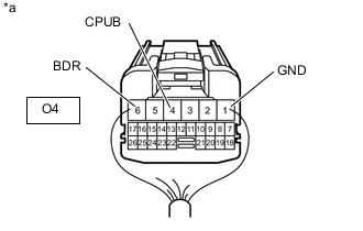
*a Rear view of wire harness connector
(to Front Multiplex Network Door ECU LH)
Disconnect the front multiplex network door ECU LH connector.
-
Measure the resistance according to the value(s) in the table below
Standard Resistance Tester Connection Condition Specified Condition O4-1 (GND) - Body
ground
Always Below 1 Ω -
Measure the resistance according to the value(s) in the table below
Standard Voltage Tester Connection Condition Specified Condition O4-4 (CPUB) - Body
ground
Always 11 to 14 V O4-6 (BDR) - Body
ground
Always 11 to 14 V Result Proceed to OK NG
OK
REPLACE FRONT MULTIPLEX NETWORK DOOR ECU LH Click here
NG
REPAIR OR REPLACE HARNESS OR CONNECTOR
-
-
READ VALUE USING GTS (DOOR KEY - LINKED LOCK AND UNLOCK SWITCH)
-
Connect the GTS to the DLC3.
-
Turn the engine switch on (IG).
-
Turn the GTS on.
-
Enter the following menus: Body Electrical / Front Right Door / Data List.
-
Read the Data List according to the display on the GTS.
Body Electrical > Front Right Door > Data ListTester Display Measurement Item Range Normal Condition Diagnostic Note Door Key Linked Lock SW Driver door key-linked lock/unlock switch lock signal OFF or ON ON: Driver door key cylinder turned to lock position
OFF: Driver door key cylinder not turned to lock position
- Door Key Linked Unlock SW Driver door key-linked lock/unlock switch unlock signal OFF or ON ON: Driver door key cylinder turned to unlock position
OFF: Driver door key cylinder not turned to unlock position
-
Body Electrical > Front Right Door > Data ListTester Display Door Lock SW Door Unlock SW Result Proceed to OK NG
OK
REPLACE FRONT MULTIPLEX NETWORK DOOR ECU RH Click here
NG
-
-
INSPECT FRONT DOOR LOCK ASSEMBLY RH
-
Remove the front door lock assembly RH.
-
Inspect the front door lock assembly RH.
Result Proceed to OK NG
NG
REPLACE FRONT DOOR LOCK ASSEMBLY RH Click here
OK
-
-
CHECK HARNESS AND CONNECTOR (FRONT MULTIPLEX NETWORK DOOR ECU RH - FRONT DOOR LOCK ASSEMBLY RH)
-
Disconnect the N27 front door lock assembly RH connector.
-
Disconnect the N3 front multiplex network door ECU RH connector.
-
Measure the resistance according to the value(s) in the table below.
Standard Resistance Tester Connection Condition Specified Condition N27-6 (L) - N3-16 (KL) Always Below 1 Ω N27-5 (UL) - N3-24 (KUL) Always Below 1 Ω N27-8 (E) - N3-22 (LSWE) Always Below 1 Ω N27-6 (L) or N3-16 (KL) - Body ground Always 10 kΩ or higher N27-5 (UL) or N3-24 (KUL) - Body ground Always 10 kΩ or higher N27-8 (E) or N3-22 (LSWE) - Body ground Always 10 kΩ or higher Result Proceed to OK NG
NG
REPAIR OR REPLACE HARNESS OR CONNECTOR
OK
-
-
CHECK HARNESS AND CONNECTOR (FRONT MULTIPLEX NETWORK DOOR ECU RH - BATTERY AND BODY GROUND)
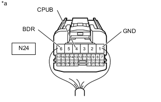
*a Rear view of wire harness connector
(to Front Multiplex Network Door ECU RH)
-
Disconnect the front multiplex network door ECU RH connector.
-
Measure the resistance according to the value(s) in the table below.
Standard Resistance Tester Connection Condition Specified Condition N24-1 (GND) - Body
ground
Always Below 1 Ω -
Measure the voltage according to the value(s) in the table below.
Standard Voltage Tester Connection Condition Specified Condition N24-4 (CPUB) - Body
ground
Always 11 to 14 V N24-6 (BDR) - Body
ground
Always 11 to 14 V Result Proceed to OK NG
OK
REPLACE FRONT MULTIPLEX NETWORK DOOR ECU RH Click here
NG
REPAIR OR REPLACE HARNESS OR CONNECTOR
-