CAN COMMUNICATION SYSTEM(for RHD) Check Bus 2 Lines for Short Circuit
DESCRIPTION
There may be a short circuit between the bus 2 CAN main wires and/or CAN branch wires when the resistance between terminals 18 (CA4H) and 17 (CA4L) of the central gateway ECU (network gateway ECU) is below 54 Ω.
| Symptom | Trouble Area |
|---|---|
| Resistance between terminals 18 (CA4H) and 17 (CA4L) of central gateway ECU (network gateway ECU) is below 54 Ω. |
|
-
*1: w/ Headup Display
WIRING DIAGRAM
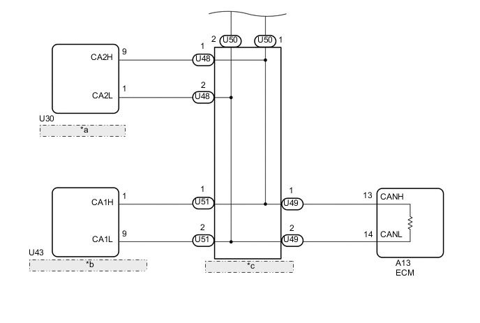
| *a | Parking Brake ECU Assembly |
| *b | Torque Vectoring Differential ECU Assembly |
| *c | No. 9 CAN Junction Connector |
CAUTION / NOTICE / HINT
Note
-
Before measuring the resistance of the CAN bus, turn the engine switch off and leave the vehicle for 1 minute or more without operating the key or any switches, or opening or closing the doors. After that, disconnect the cable from the negative (-) battery terminal and leave the vehicle for 1 minute or more before measuring the resistance.
-
After turning the engine switch off, waiting time may be required before disconnecting the cable from the negative (-) battery terminal. Therefore, make sure to read the disconnecting the cable from the negative (-) battery terminal notices before proceeding with work.
-
Because the order of diagnosis is important to allow correct diagnosis, make sure to begin troubleshooting using How to Proceed with Troubleshooting when CAN communication system related DTCs are output.
-
After performing repairs, perform the DTC check procedure and confirm that the DTCs are not output again.
-
DTC check procedure: Turn the engine switch on (IG), wait at least 60 seconds, and then drive the vehicle at a speed of 40 km/h (25 mph) or more for 5 minutes or more.
-
After the repair, perform the CAN bus check and check that all the ECUs and sensors connected to the CAN communication system are displayed as normal.
-
Before replacing the ECM, certification ECU (smart key ECU assembly) or main body ECU (multiplex network body ECU), refer to Service Bulletin.
Tech Tips
-
Operating the engine switch, any other switches or a door triggers related ECU and sensor communication on the CAN. This communication will cause the resistance value to change.
-
Even after DTCs are cleared, if a DTC is stored again after driving the vehicle for a while, the malfunction may be occurring due to vibration of the vehicle. In such a case, wiggling the ECUs or wire harness while performing the inspection below may help determine the cause of the malfunction.
PROCEDURE
-
CHECK FOR SHORT IN CAN BUS WIRE (ECM - NO. 9 CAN JUNCTION CONNECTOR)
-
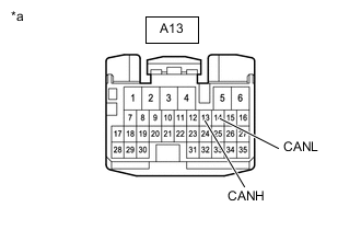
*a Front view of wire harness connector
(to ECM)
Disconnect the cable from the negative (-) battery terminal.
-
Disconnect the ECM connector.
-
Measure the resistance according to the value(s) in the table below.
Standard Resistance Tester Connection Condition Specified Condition A13-13 (CANH) - A13-14 (CANL) Cable disconnected from negative (-) battery terminal 108 to 132 Ω Result Proceed to OK NG
OK 
REPLACE ECM Click here
NG 
-
-
CONNECT CONNECTOR
-
Reconnect the A13 ECM connector.
Result Proceed to NEXT
NEXT
-
-
CHECK FOR SHORT IN CAN BUS WIRE (COMBINATION METER ASSEMBLY - NO. 3 CAN JUNCTION CONNECTOR)
-
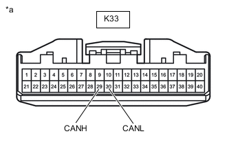
*a Front view of wire harness connector
(to Combination Meter Assembly)
Disconnect the combination meter assembly connector.
-
Measure the resistance according to the value(s) in the table below.
Standard Resistance Tester Connection Condition Specified Condition K33-29 (CANH) - K33-30 (CANL) Cable disconnected from negative (-) battery terminal 108 to 132 Ω Result Proceed to OK NG
OK
REPLACE COMBINATION METER ASSEMBLY Click here
NG
-
-
CONNECT CONNECTOR
-
Reconnect the K33 combination meter assembly connector.
Result Proceed to NEXT
NEXT
-
-
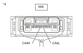
CHECK FOR SHORT IN CAN BUS WIRE (CENTRAL GATEWAY ECU (NETWORK GATEWAY ECU) - NO. 3 CAN JUNCTION CONNECTOR)
-
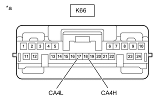
*a Front view of wire harness connector
(to Central Gateway ECU (Network Gateway ECU))
Disconnect the central gateway ECU (network gateway ECU) connector.
-
Measure the resistance according to the value(s) in the table below.
Standard Resistance Tester Connection Condition Specified Condition K66-18 (CA4H) - K66-17 (CA4L) Cable disconnected from negative (-) battery terminal 54 to 69 Ω Result Proceed to OK NG
OK
REPLACE CENTRAL GATEWAY ECU (NETWORK GATEWAY ECU) Click here
NG
-
-
CONNECT CONNECTOR
-
Reconnect the K66 central gateway ECU (network gateway ECU) connector.
Result Proceed to NEXT
NEXT
-
-
CHECK FOR SHORT IN CAN BUS WIRES (NO. 9 CAN JUNCTION CONNECTOR)
-
Disconnect the No. 9 CAN junction connectors.
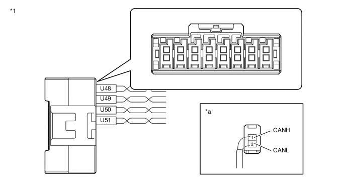
*1 No. 9 CAN Junction Connector - - *a Rear view of wire harness connector
(to No. 9 CAN Junction Connector)
- - Code Color (CANH Side) Color (CANL Side) Connect to U48 B W Parking Brake ECU Assembly U49 R W ECM U50 G W No. 2 CAN Junction Connector U51 L W Torque Vectoring Differential ECU Assembly -
Measure the resistance according to the value(s) in the table below.
Standard Resistance Tester Connection Condition Specified Condition Connected to U48-1 (CANH) - U48-2 (CANL) Cable disconnected from negative (-) battery terminal 200 Ω or higher Parking brake ECU assembly U49-1 (CANH) - U49-2 (CANL) Cable disconnected from negative (-) battery terminal 108 to 132 Ω ECM U50-1 (CANH) - U50-2 (CANL) Cable disconnected from negative (-) battery terminal 108 to 132 Ω No. 2 CAN junction connector U51-1 (CANH) - U51-2 (CANL) Cable disconnected from negative (-) battery terminal 200 Ω or higher Torque vectoring differential ECU assembly Result Result Proceed to OK A NG (ECM CAN main wire) B NG (No. 3 CAN junction connector CAN main wire) C NG (ECU or sensor CAN branch wire) D
A
REPLACE NO. 9 CAN JUNCTION CONNECTOR
B
REPAIR OR REPLACE CAN MAIN WIRE OR CONNECTOR (NO. 9 CAN JUNCTION CONNECTOR - ECM)
D 
GO TO STEP 12 Click here
C
-
-
CONNECT CONNECTOR
-
Reconnect the U48, U49, U50 and U51 No. 9 CAN junction connectors.
Result Proceed to NEXT
NEXT
-
-
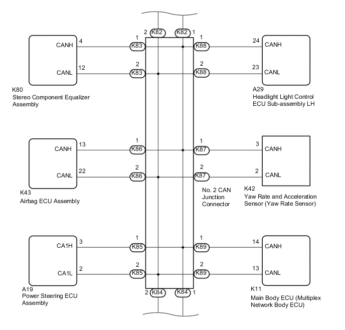
CHECK FOR SHORT IN CAN BUS WIRES (NO. 2 CAN JUNCTION CONNECTOR)
-
Disconnect the No. 2 CAN junction connectors.
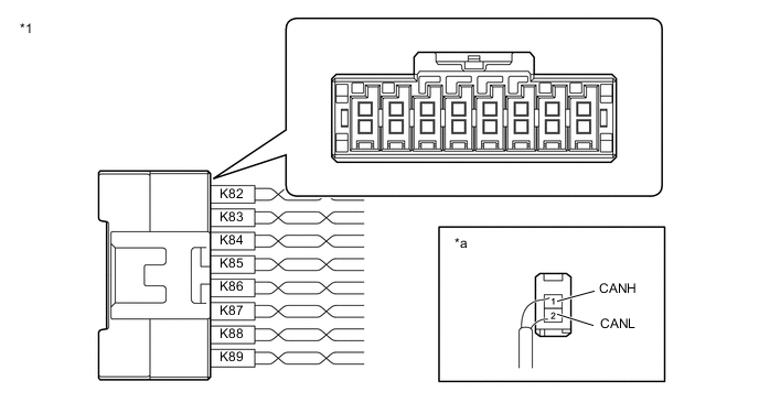
*1 No. 2 CAN Junction Connector - - *a Rear view of wire harness connector
(to No. 2 CAN Junction Connector)
- - Code Color (CANH Side) Color (CANL Side) Connect to K82 B W No. 3 CAN Junction Connector K83 R W Stereo Component Equalizer Assembly K84 G W No. 9 CAN Junction Connector K85 L W Power Steering ECU Assembly K86 Y W Airbag ECU Assembly K87 V W Yaw Rate and Acceleration Sensor (Yaw Rate Sensor) K88 P W Headlight Light Control ECU Sub-assembly LH K89 BE W Main Body ECU (Multiplex Network Body ECU) -
Measure the resistance according to the value(s) in the table below.
Standard Resistance Tester Connection Condition Specified Condition Connected to K82-1 (CANH) - K82-2 (CANL) Cable disconnected from negative (-) battery terminal 108 to 132 Ω No. 3 CAN junction connector K83-1 (CANH) - K83-2 (CANL) Cable disconnected from negative (-) battery terminal 200 Ω or higher Stereo component equalizer assembly K84-1 (CANH) - K84-2 (CANL) Cable disconnected from negative (-) battery terminal 108 to 132 Ω No. 9 CAN junction connector K85-1 (CANH) - K85-2 (CANL) Cable disconnected from negative (-) battery terminal 200 Ω or higher Power steering ECU assembly K86-1 (CANH) - K86-2 (CANL) Cable disconnected from negative (-) battery terminal 200 Ω or higher Airbag ECU assembly K87-1 (CANH) - K87-2 (CANL) Cable disconnected from negative (-) battery terminal 200 Ω or higher Yaw rate and acceleration sensor (yaw rate sensor) K88-1 (CANH) - K88-2 (CANL) Cable disconnected from negative (-) battery terminal 200 Ω or higher Headlight light control ECU sub-assembly LH K89-1 (CANH) - K89-2 (CANL) Cable disconnected from negative (-) battery terminal 200 Ω or higher Main body ECU (multiplex network body ECU) Result Result Proceed to OK A NG (No. 9 CAN junction connector CAN main wire) B NG (No. 3 CAN junction connector CAN main wire) C NG (ECU or sensor CAN branch wires) D
A
REPLACE NO. 2 CAN JUNCTION CONNECTOR
B
REPAIR OR REPLACE CAN MAIN WIRE OR CONNECTOR (NO. 2 CAN JUNCTION CONNECTOR - NO. 9 CAN JUNCTION CONNECTOR)
D
GO TO STEP 12 Click here
C
-
-
CONNECT CONNECTOR
-
Reconnect the K82, K83, K84, K85, K86, K87, K88 and K89 No. 2 CAN junction connectors.
Result Proceed to NEXT
NEXT
-
-
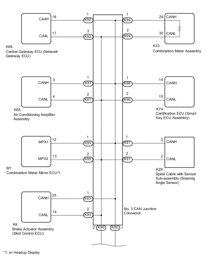
CHECK FOR SHORT IN CAN BUS WIRES (NO. 3 CAN JUNCTION CONNECTOR)
-
Disconnect the No. 3 CAN junction connectors.

*1 No. 3 CAN Junction Connector - - *a Rear view of wire harness connector
(to No. 3 CAN Junction Connector)
- - Code Color (CANH Side) Color (CANL Side) Connect to K90 B W No. 2 CAN Junction Connector K91 R W Spiral Cable with Sensor Sub-assembly (Steering Angle Sensor) K92 G W Central Gateway ECU (Network Gateway ECU) K93 L W Brake Actuator Assembly (Skid Control ECU) K94 Y W Combination Meter Assembly K95 V W Combination Meter Mirror ECU*1 K96 P W Certification ECU (Smart Key ECU Assembly) K97 BE W Air Conditioning Amplifier Assembly
-
*1: w/ Headup Display
-
-
Measure the resistance according to the value(s) in the table below.
Standard Resistance Tester Connection Condition Specified Condition Connected to K90-1 (CANH) - K90-2 (CANL) Cable disconnected from negative (-) battery terminal 108 to 132 Ω No. 2 CAN junction connector K91-1 (CANH) - K91-2 (CANL) Cable disconnected from negative (-) battery terminal 200 Ω or higher Spiral cable with sensor sub-assembly (steering angle sensor) K92-1 (CANH) - K92-2 (CANL) Cable disconnected from negative (-) battery terminal 54 to 69 Ω Central gateway ECU (network gateway ECU) K93-1 (CANH) - K93-2 (CANL) Cable disconnected from negative (-) battery terminal 200 Ω or higher Brake actuator assembly (skid control ECU) K94-1 (CANH) - K94-2 (CANL) Cable disconnected from negative (-) battery terminal 108 to 132 Ω Combination meter assembly K95-1 (CANH) - K95-2 (CANL) Cable disconnected from negative (-) battery terminal 200 Ω or higher Combination meter mirror ECU*1 K96-1 (CANH) - K96-2 (CANL) Cable disconnected from negative (-) battery terminal 200 Ω or higher Certification ECU (smart key ECU assembly) K97-1 (CANH) - K97-2 (CANL) Cable disconnected from negative (-) battery terminal 200 Ω or higher Air conditioning amplifier assembly
-
*1: w/ Headup Display
Result Result Proceed to OK A NG (central gateway ECU (network gateway ECU) CAN branch wire) B NG (No. 3 CAN junction connector CAN main wire) C NG (combination meter assembly CAN main wire) D NG (ECU or sensor CAN branch wires) E -
A
REPLACE NO. 3 CAN JUNCTION CONNECTOR
B
REPAIR OR REPLACE CAN BRANCH WIRE OR CONNECTOR (NO. 3 CAN JUNCTION CONNECTOR - CENTRAL GATEWAY ECU (NETWORK GATEWAY ECU))
C
REPAIR OR REPLACE CAN MAIN WIRE OR CONNECTOR (NO. 3 CAN JUNCTION CONNECTOR - NO. 2 CAN JUNCTION CONNECTOR)
D
REPAIR OR REPLACE CAN MAIN WIRE OR CONNECTOR (NO. 3 CAN JUNCTION CONNECTOR - COMBINATION METER ASSEMBLY)
E
-
-
CHECK FOR SHORT IN CAN BUS WIRES (ECU, SENSOR)
-
*a Component with harness connected
(Central Gateway ECU (Network Gateway ECU))
Reconnect the CAN junction connector.
-
Disconnect the connector that includes terminals CANH and CANL from the ECU or sensor to which the short circuited CAN branch wire is connected.
-
Measure the resistance according to the value(s) in the table below.
Standard Resistance Tester Connection Condition Specified Condition K66-18 (CA4H) - K66-17 (CA4L) Cable disconnected from negative (-) battery terminal 54 to 69 Ω Tech Tips
If the resistance becomes normal (between 54 and 69 Ω) when the connector is disconnected from the ECU or sensor, there may be a short in the ECU or sensor.
Result Proceed to OK NG
OK
REPAIR OR REPLACE CORRESPONDING ECU OR SENSOR CAN BRANCH WIRES OR CONNECTOR
NG
REPLACE CORRESPONDING ECU OR SENSOR
-