CAN COMMUNICATION SYSTEM(for LHD), Diagnostic DTC:U0230
| DTC Code | DTC Name |
|---|---|
| U0230 | Lost Communication with Rear Gate Module |
DESCRIPTION
| DTC No. | Detection Item | DTC Detection Condition | Trouble Area | DTC Output from |
|---|---|---|---|---|
| U0230 | Lost Communication with Rear Gate Module | There is no communication from the luggage closer motor assembly*1 or multiplex network door ECU*2. |
|
Main body ECU (multiplex network body ECU) |
-
*1: w/ Power Trunk Lid System
-
*2: w/o Power Trunk Lid System
WIRING DIAGRAM
-
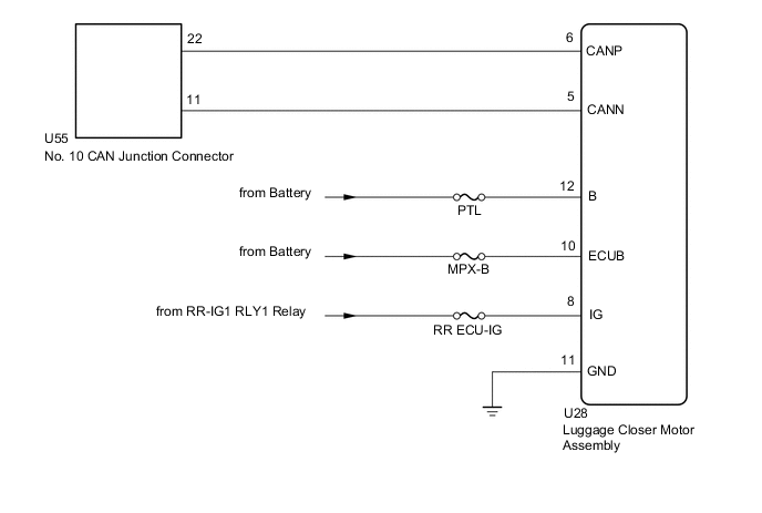
w/ Power Trunk Lid System
-
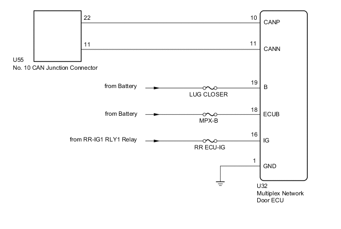
w/o Power Trunk Lid System
CAUTION / NOTICE / HINT
Note
-
Before measuring the resistance of the CAN bus, turn the engine switch off and leave the vehicle for 1 minute or more without operating the key or any switches, or opening or closing the doors. After that, disconnect the cable from the negative (-) battery terminal and leave the vehicle for 1 minute or more before measuring the resistance.
-
After turning the engine switch off, waiting time may be required before disconnecting the cable from the negative (-) battery terminal. Therefore, make sure to read the disconnecting the cable from the negative (-) battery terminal notices before proceeding with work.
-
Because the order of diagnosis is important to allow correct diagnosis, make sure to begin troubleshooting using How to Proceed with Troubleshooting when CAN communication system related DTCs are output.
-
After performing repairs, perform the DTC check procedure and confirm that the DTCs are not output again.
-
DTC check procedure: Turn the engine switch on (IG) and wait at least 20 seconds.
-
After the repair, perform the CAN bus check and check that all the ECUs and sensors connected to the CAN communication system are displayed.
-
Inspect the fuses for circuits related to this system before performing the following procedure.
Tech Tips
-
Operating the engine switch, any other switches or a door triggers related ECU and sensor communication on the CAN. This communication will cause the resistance value to change.
-
Even after DTCs are cleared, if a DTC is stored again after driving the vehicle for a while, the malfunction may be occurring due to vibration of the vehicle. In such a case, wiggling the ECUs or wire harness while performing the inspection below may help determine the cause of the malfunction.
PROCEDURE
-
SYSTEM CHECK
-
Check the vehicle specifications.
Result Result Proceed to w/ Power Trunk Lid System A w/o Power Trunk Lid System B
B 
CHECK FOR DTC Click here
A 
-
-
CHECK FOR DTC
-
Check for DTCs.
Body Electrical > Main Body > Trouble CodesTech Tips
If DTC U1002 is output from the gateway of the main body ECU (multiplex network body ECU), this indicates a sub bus 1 malfunction. Troubleshoot for DTC U1002 and check for malfunctions in sub bus 1.
Result Result Proceed to DTC U1002 is not output from main body ECU (multiplex network body ECU) A DTC U1002 is output from main body ECU (multiplex network body ECU) B
B 
GO TO DIAGNOSIS PROCEDURE INDICATED BY OUTPUT DTC Click here
A
-
-
CHECK FOR OPEN IN CAN BUS WIRE (LUGGAGE CLOSER MOTOR ASSEMBLY BRANCH WIRE)
-
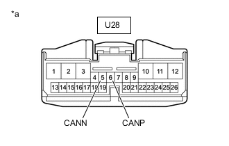
*a Front view of wire harness connector
(to Luggage Closer Motor Assembly)
Disconnect the cable from the negative (-) battery terminal.
-
Disconnect the luggage closer motor assembly connector.
-
Measure the resistance according to the value(s) in the table below.
Standard Resistance Tester Connection Condition Specified Condition U28-6 (CANP) - U28-5 (CANN) Cable disconnected from negative (-) battery terminal 54 to 69 Ω Result Proceed to OK NG
NG
REPAIR OR REPLACE CAN BRANCH WIRE OR CONNECTOR (LUGGAGE CLOSER MOTOR ASSEMBLY)
OK
-
-
CHECK HARNESS AND CONNECTOR (LUGGAGE CLOSER MOTOR ASSEMBLY - BATTERY AND BODY GROUND)
-
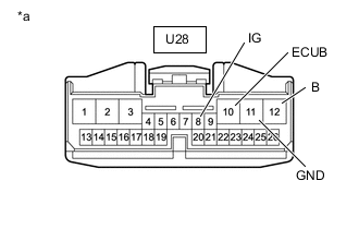
*a Front view of wire harness connector
(to Luggage Closer Motor Assembly)
Reconnect the cable to the negative (-) battery terminal.
Note
When disconnecting the cable, some systems need to be initialized after the cable is reconnected.
-
Disconnect the luggage closer motor assembly connector.
-
Measure the voltage according to the value(s) in the table below.
Standard Voltage Tester Connection Switch Condition Specified Condition U28-10 (ECUB) - Body ground Always 11 to 14 V U28-12 (B) - Body ground Always 11 to 14 V U28-8 (IG) - Body ground Engine switch on (IG) 11 to 14 V -
Measure the resistance according to the value(s) in the table below.
Standard Resistance Tester Connection Condition Specified Condition U28-11 (GND) - Body ground Always Below 1 Ω Result Proceed to OK NG
OK
REPLACE LUGGAGE CLOSER MOTOR ASSEMBLY Click here
NG
REPAIR OR REPLACE HARNESS OR CONNECTOR
-
-
CHECK FOR DTC
-
Check for DTCs.
Body Electrical > Main Body > Trouble CodesTech Tips
If DTC U1002 is output from the gateway of the main body ECU (multiplex network body ECU), this indicates a sub bus 1 malfunction. Troubleshoot for DTC U1002 and check for malfunctions in sub bus 1.
Result Result Proceed to DTC U1002 is not output from main body ECU (multiplex network body ECU) A DTC U1002 is output from main body ECU (multiplex network body ECU) B
B
GO TO DIAGNOSIS PROCEDURE INDICATED BY OUTPUT DTC Click here
A
-
-
CHECK FOR OPEN IN CAN BUS WIRE (MULTIPLEX NETWORK DOOR ECU BRANCH WIRE)
-
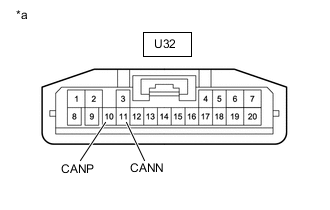
*a Front view of wire harness connector
(to Multiplex Network Door ECU)
Disconnect the cable from the negative (-) battery terminal.
-
Disconnect the multiplex network door ECU connector.
-
Measure the resistance according to the value(s) in the table below.
Standard Resistance Tester Connection Condition Specified Condition U32-10 (CANP) - U32-11 (CANN) Cable disconnected from negative (-) battery terminal 54 to 69 Ω Result Proceed to OK NG
NG
REPAIR OR REPLACE CAN BRANCH WIRE OR CONNECTOR (MULTIPLEX NETWORK DOOR ECU)
OK
-
-
CHECK HARNESS AND CONNECTOR (MULTIPLEX NETWORK DOOR ECU - BATTERY AND BODY GROUND)
-
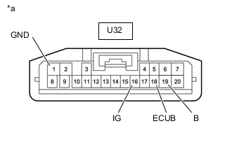
*a Front view of wire harness connector
(to Multiplex Network Door ECU)
Reconnect the cable to the negative (-) battery terminal.
Note
When disconnecting the cable, some systems need to be initialized after the cable is reconnected.
-
Disconnect the multiplex network door ECU connector.
-
Measure the voltage according to the value(s) in the table below.
Standard Voltage Tester Connection Switch Condition Specified Condition U32-18 (ECUB) - Body ground Always 11 to 14 V U32-19 (B) - Body ground Always 11 to 14 V U32-16 (IG) - Body ground Engine switch on (IG) 11 to 14 V -
Measure the resistance according to the value(s) in the table below.
Standard Resistance Tester Connection Condition Specified Condition U32-1 (GND) - Body ground Always Below 1 Ω Result Proceed to OK NG
OK
REPLACE MULTIPLEX NETWORK DOOR ECU Click here
NG
REPAIR OR REPLACE HARNESS OR CONNECTOR
-