LIN COMMUNICATION SYSTEM TERMINALS OF ECU
-
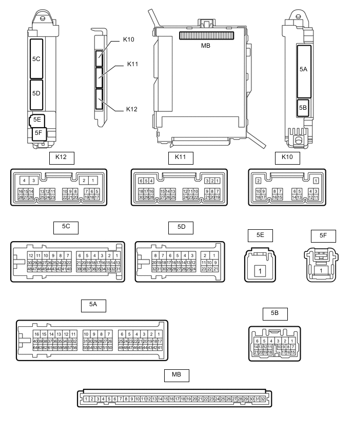
CHECK COWL SIDE JUNCTION BLOCK ASSEMBLY LH AND MAIN BODY ECU (MULTIPLEX NETWORK BODY ECU)
-
Remove the main body ECU (multiplex network body ECU).
-
Connect the cowl side junction block assembly LH connectors.
-
Measure the voltage and resistance according to the value(s) in the table below.
Tech Tips
Measure the values on the wire harness side with the connectors disconnected.
Tester Connection Wiring Color Terminal Description Condition Specified Condition MB-11 (GND1) - Body ground - Ground Always Below 1 Ω MB-30 (BECU) - Body ground - Battery power supply Always 11 to 14 V MB-29 (ACC) - Body ground - ACC power supply Engine switch on (ACC) 11 to 14 V MB-29 (ACC) - Body ground - ACC power supply Engine switch off Below 1 V MB-32 (IG) - Body ground - IG power supply Engine switch on (IG) 11 to 14 V MB-32 (IG) - Body ground - IG power supply Engine switch off Below 1 V
-
-
CHECK FRONT MULTIPLEX NETWORK DOOR ECU LH

-
Disconnect the O4 front multiplex network door ECU LH connector.
-
Measure the voltage and resistance according to the value(s) in the table below.
Terminal No. (Symbol) Wiring Color Terminal Description Condition Specified Condition O4-4(CPUB) - O4-1(GND) P - W-B Battery power supply Always 11 to 14 V O4-6(BDR) - O4-1(GND) V - W-B Battery power supply Always 11 to 14 V O4-16(BCUT) - O4-1(GND)*1 L - W-B Battery power supply Always 11 to 14 V O4-3(SIG) - O4-1(GND) B - W-B IG power supply Engine switch on (IG) 11 to 14 V O4-1(GND) - Body ground W-B - Body ground Ground Always Below 1 V
-
*1: for LHD
If the result is not as specified, there may be a malfunctioning in the wire harness.
-
-
-
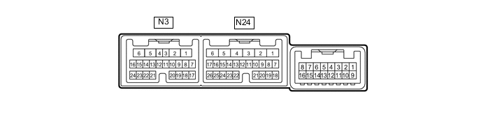
CHECK FRONT MULTIPLEX NETWORK DOOR ECU RH
-
Disconnect the N24 front multiplex network door ECU RH connector.
-
Measure the voltage and resistance according to the value(s) in the table below.
Terminal No. (Symbol) Wiring Color Terminal Description Condition Specified Condition N24-6 (BDR) - Body ground V - Body ground Battery power supply Always 11 to 14 V N24-4 (CPUB) - Body ground P - Body ground Battery power supply Always 11 to 14 V N26-16 (BCUT) - Body ground*1 L - Body ground Battery power supply Always 11 to 14 V N24-3 (SIG) - N24-1 (GND) B - W-B IG power supply Engine switch on (IG) 11 to 14 V N24-1 (GND) - Body ground W-B - Body ground Ground Always Below 1 V
-
*1: for RHD
If the result is not as specified, the main body ECU (multiplex network body ECU) or instrument panel junction block assembly may be malfunctioning.
-
-
-
CHECK POWER WINDOW REGULATOR MASTER SWITCH ASSEMBLY
-
Disconnect the O10*1 or N30*2 power window regulator master switch assembly connector.
-
*1: for LHD
-
*2: for RHD

*A for LHD *B for RHD -
-
Measure the voltage and resistance according to the value(s) in the table below.
Tech Tips
Measure the values on the wire harness side with the connector disconnected.
for LHD Tester Connection Wiring Color Terminal Description Condition Specified Condition O10-11 (B) - O10-12 (GND) P - W-B Power supply Always 11 to 14 V O10-12 (GND) - Body ground W-B - Body ground Ground Always Below 1 Ω for RHD Tester Connection Wiring Color Terminal Description Condition Specified Condition N30-11 (B) - N30-12 (GND) P - W-B Power supply Always 11 to 14 V N30-12 (GND) - Body ground W-B - Body ground Ground Always Below 1 Ω If the result is not as specified, there may be a malfunction in the wire harness.
-
-
CHECK FRONT POWER WINDOW REGULATOR MOTOR ASSEMBLY (FOR DRIVER DOOR)
-
Disconnect the O2*1 or N2*2 power window regulator motor assembly (for driver door) connector.
-
*1: for LHD
-
*2: for RHD

*A for LHD *B for RHD -
-
Measure the voltage and resistance according to the value(s) in the table below.
Tech Tips
Measure the values on the wire harness side with the connector disconnected.
for LHD Tester Connection Wiring Color Terminal Description Condition Specified Condition O2-1 (E) - Body ground BR - Body ground Ground Always Below 1 Ω O2-2 (B) - Body ground R - Body ground Power supply Always 11 to 14 V for RHD Tester Connection Wiring Color Terminal Description Condition Specified Condition N2-1 (E) - Body ground BR - Body ground Ground Always Below 1 Ω N2-2 (B) - Body ground R - Body ground Power supply Always 11 to 14 V If the result is not as specified, there may be a malfunction in the wire harness.
-
-
CHECK FRONT POWER WINDOW REGULATOR MOTOR ASSEMBLY (FOR FRONT PASSENGER DOOR)
-
Disconnect the N2*1 or O2*2 power window regulator motor assembly (for front passenger door) connector.
-
*1: for LHD
-
*2: for RHD

*A for LHD *B for RHD -
-
Measure the voltage and resistance according to the value(s) in the table below.
Tech Tips
Measure the values on the wire harness side with the connector disconnected.
for LHD Tester Connection Wiring Color Terminal Description Condition Specified Condition N2-1 (E) - Body ground BR - Body ground Ground Always Below 1 Ω N2-2 (B) - Body ground R - Body ground Power supply Always 11 to 14 V for RHD Tester Connection Wiring Color Terminal Description Condition Specified Condition O2-1 (E) - Body ground BR - Body ground Ground Always Below 1 Ω O2-2 (B) - Body ground R - Body ground Power supply Always 11 to 14 V If the result is not as specified, there may be a malfunction in the wire harness.
-
-
CHECK REAR POWER WINDOW REGULATOR MOTOR ASSEMBLY (FOR REAR LH DOOR)
-
Disconnect the Q1 power window regulator motor assembly (for rear LH door) connector.

-
Measure the voltage and resistance according to the value(s) in the table below.
Tech Tips
Measure the values on the wire harness side with the connector disconnected.
Tester Connection Wiring Color Terminal Description Condition Specified Condition Q1-1 (E) - Body ground W-B - Body ground Ground Always Below 1 Ω Q1-2 (B) - Body ground R - Body ground Power supply Always 11 to 14 V If the result is not as specified, there may be a malfunction in the wire harness.
-
-
CHECK REAR POWER WINDOW REGULATOR MOTOR ASSEMBLY (FOR REAR RH DOOR)
-
Disconnect the P1 power window regulator motor assembly (for rear RH door) connector.

-
Measure the voltage and resistance according to the value(s) in the table below.
Tech Tips
Measure the values on the wire harness side with the connector disconnected.
Tester Connection Wiring Color Terminal Description Condition Specified Condition P1-1 (E) - Body ground W-B - Body ground Ground Always Below 1 Ω P1-2 (B) - Body ground R - Body ground Power supply Always 11 to 14 V If the result is not as specified, there may be a malfunction in the wire harness.
-
-
CHECK SLIDING ROOF DRIVE GEAR SUB-ASSEMBLY (w/ Sliding Roof System)

-
Disconnect the W4 sliding roof ECU (sliding roof drive gear sub-assembly) connector.
-
Measure the resistance and voltage according to the value(s) in the table below.
Tech Tips
Measure the values on the wire harness side with the connector disconnected.
Terminal No. (Symbol) Wiring Color Terminal Description Condition Specified Condition W4-8 (B) - W4-12 (E) L - W-B Battery power supply Always 11 to 14 V W4-12 (E) - Body ground W-B - Body ground Ground Always Below 1 Ω If the result is not as specified, there may be a malfunction in the wire harness.
-
-
CHECK CERTIFICATION ECU (SMART KEY ECU ASSEMBLY)

*A for LHD *B for RHD
-
Disconnect the A21 and K74 certification ECU (smart key ECU assembly) connectors.
-
Measure the resistance and voltage according to the value(s) in the table below.
Terminal No. (Symbol) Wiring Color Terminal Description Condition Specified Condition A21-2 (+B) - Body ground W - Body ground Battery power supply Always 11 to 14 V K74-5 (IG) - Body ground B - Body ground Ignition power supply Engine switch off Below 1 V Engine switch on (IG) 11 to 14 V A21-10 (CUTB) - Body ground P - Body ground Dark current cut fuse pin input signal Always 11 to 14 V A21-11 (E) - Body ground W-B - Body ground Ground Always Below 1 Ω
-
-
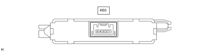
CHECK ID CODE BOX (IMMOBILISER CODE BOX)
-
Disconnect the K60 ID code box connector.
-
Measure the resistance and voltage according to the value(s) in the table below.
Terminal No. (Symbol) Wiring Color Terminal Description Condition Specified Condition K60-1 (+B) - Body ground GR - Body ground Battery power supply Always 11 to 14 V K60-5 (GND) - Body ground W-B - Body ground Ground Always Below 1 Ω
-
-
CHECK STEERING LOCK ACTUATOR ASSEMBLY

-
Disconnect the K20 steering lock actuator assembly connector.
-
Measure the resistance and voltage according to the value(s) in the table below.
Terminal No. (Symbol) Wiring Color Terminal Description Condition Specified Condition K20-7 (B) - Body ground W - Body ground Battery power supply Always 11 to 14 V K20-1 (GND) - Body ground W-B - Body ground Ground Always Below 1 Ω
-
-
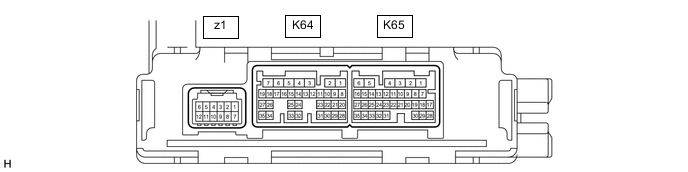
CHECK AIR CONDITIONING AMPLIFIER ASSEMBLY
-
Disconnect the K64 air conditioning amplifier assembly connector.
-
Measure the resistance and voltage according to the value(s) in the table below.
Terminal No. (Symbol) Wiring Color Terminal Description Condition Specified Condition K64-5 (IG+) - Body ground B - Body ground IG power supply Engine switch off Below 1 V K64-5 (IG+) - Body ground B - Body ground IG power supply Engine switch on (IG) 11 to 14 V K64-6 (+B1) - Body ground W - Body ground Battery power supply Always 11 to 14 V K64-1 (GND) - Body ground W-B - Body ground Ground Always Below 1 Ω
-
-
CHECK REFRESHING SEAT SWITCH (w/ Refreshing Seat Switch)
-
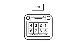
Disconnect the K59 refreshing seat switch connector.
-
Measure the resistance and voltage according to the value(s) in the table below.
Terminal No. (Symbol) Wiring Color Terminal Description Condition Specified Condition K59-4 (E) - Body ground W-B - Body ground Ground Always Below 1 Ω K59-1 (IG) - Body ground W - Body ground IG power supply Engine switch on (IG) 11 to 14 V
-
-
CHECK REAR CONTROL SWITCH (w/ Rear Control Switch)
-
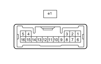
Disconnect the e1 rear control switch connector.
-
Measure the resistance and voltage according to the value(s) in the table below.
Terminal No. (Symbol) Wiring Color Terminal Description Condition Specified Condition e1-5 (E) - Body ground W-B - Body ground Ground Always Below 1 Ω e1-7 (IG+) - Body ground L - Body ground IG power supply Engine switch on (IG) 11 to 14 V
-
-
CHECK RAIN SENSOR (w/ Rain Sensor)

-
Disconnect the W5 rain sensor connector.
-
Measure the resistance and voltage according to the value(s) in the table below.
Terminal No. (Symbol) Wiring Color Terminal Description Condition Specified Condition W5-4 (SIG) - Body ground B - Body ground IG power supply Engine switch on (IG) 11 to 14 V W5-2 (ES) - Body ground W - Body ground Ground circuit Always Below 1 Ω
-
-
CHECK WINDSHIELD WIPER SWITCH ASSEMBLY
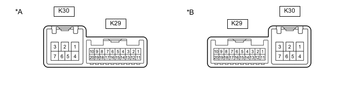
*A for LH Side *B for RH Side
-
Disconnect the K29 windshield wiper switch assembly connector.
-
Measure the resistance and voltage according to the value(s) in the table below.
Terminal No. (Symbol) Wiring Color Terminal Description Condition Specified Condition K29-7 (E) - Body ground W-B - Body ground Ground Always Below 1 Ω K29-2 (+B) - K29-7 (E) SB - W-B Battery power supply Engine switch on (IG) 11 to 14 V
-
-
CHECK HEADLIGHT LIGHT CONTROL ECU SUB-ASSEMBLY LH
-
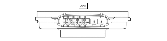
Disconnect the A29 headlight light control ECU sub-assembly LH connector.
-
Measure the resistance and voltage according to the value(s) in the table below.
Terminal No. (Symbol) Wiring Color Terminal Description Condition Specified Condition A29-4 (IG) - Body ground LG - Body ground IG power supply Engine switch off Below 1 V Engine switch on (IG) 11 to 14 V A29-13 (ECUB) - Body ground G - Body ground Battery power supply Engine switch off and light switch off Below 1 V Engine switch on (IG) or light switch on 11 to 14 V A29-12 (GND) - Body ground W-B - Body ground Ground Always Below 1 Ω
-
-
CHECK HEADLIGHT LIGHT CONTROL ECU SUB-ASSEMBLY RH

-
Disconnect the A30 headlight light control ECU sub-assembly RH connector.
-
Measure the resistance and voltage according to the value(s) in the table below.
Terminal No. (Symbol) Wiring Color Terminal Description Condition Specified Condition A30-4 (IG) - Body ground LG - Body ground IG power supply Engine switch off Below 1 V Engine switch on (IG) 11 to 14 V A30-13 (ECUB) - Body ground B - Body ground Battery power supply Engine switch off and light switch off Below 1 V Engine switch on (IG) or light switch on 11 to 14 V A30-12 (GND) - Body ground W-B - Body ground Ground Always Below 1 Ω
-