MAIN BODY ECU REMOVAL
CAUTION / NOTICE / HINT
The necessary procedures (adjustment, calibration, initialization, or registration) that must be performed after parts are removed, installed, or replaced during the main body ECU removal/installation are shown below.
| Replacement Part or Procedure | Necessary Procedure | Effect/Inoperative when not Performed | Link |
|---|---|---|---|
| Disconnect cable from negative battery terminal | Memorize steering angle neutral point | Parking assist monitor system | |
| LKA/LDA system | |||
| Pre-crash safety system | |||
| Adaptive high beam system | |||
| Reset power trunk lid | Power trunk lid system | ||
| Main body ECU (multiplex network body ECU) | Code registration (Immobiliser system) |
|
See the Service Bulletin for the registration method. |
PROCEDURE
-
REMOVE LOWER NO. 1 INSTRUMENT PANEL AIRBAG ASSEMBLY (for LHD)
-
REMOVE GLOVE COMPARTMENT DOOR ASSEMBLY (for RHD)
-
REMOVE COWL SIDE JUNCTION BLOCK LH (for LHD)
-
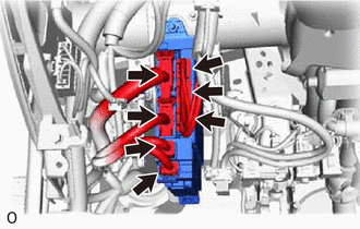
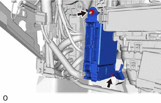
Disconnect the 7 connectors on the front side.
-
Remove the bolt and nut.
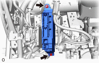
-
Disconnect the 2 connectors to remove the cowl side junction block LH on the back side.
-
-
REMOVE COWL SIDE JUNCTION BLOCK LH (for RHD)
-
Disconnect the 7 connectors on the front side.
-
Remove the bolt and nut.
-
Disconnect the 2 connectors to remove the cowl side junction block LH on the back side.
-
-
REMOVE MAIN BODY ECU (MULTIPLEX NETWORK BODY ECU)
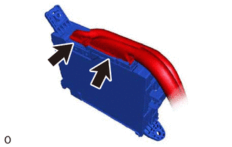
-
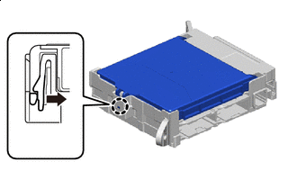

Press Press the claw of the cowl side junction block LH as shown in the illustration to release the lock.
-
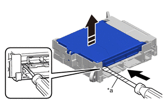
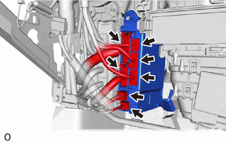
*a Protective Tape Insert 
Remove in this Direction With the cowl side junction block assembly LH lock released, insert a screwdriver with its tip wrapped in protective tape horizontally between the main body ECU (multiplex network body ECU) and cowl side junction block LH.
Note
Use a screwdriver with a diameter between 5.0 mm (0.197 in.) and 6.3 mm (0.248 in.) and a length of approximately 90 mm (3.54 in.).
-
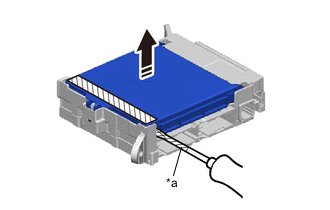
*a Protective Tape 
Connector Remove in this Direction Using a screwdriver with its tip wrapped in protective tape, carefully raise the main body ECU(multiplex network body ECU) to the position where the connector becomes disconnected.
Note
-
Do not twist the screwdriver to raise the main body ECU (multiplex network body ECU).
-
Do not damage the connector
-
-
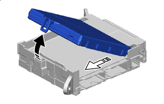
Remove in this Direction (1) 
Remove in this Direction (2) Remove the main body ECU (multiplex network body ECU) as shown in the illustration.
Note
Do not touch the main body ECU (multiplex network body ECU) connector.
-