CAN COMMUNICATION SYSTEM(for LHD) TERMINALS OF ECU
Tech Tips
Operating the engine switch, any switches or any doors triggers related ECU and sensor communication with the CAN, which causes resistance variation.
-
DISCONNECT CABLE FROM NEGATIVE BATTERY TERMINAL
-
Disconnect the cable from the negative (-) battery terminal before measuring the resistances of the CAN main wire and CAN branch wire.
CAUTION:
Wait at least 90 seconds after disconnecting the cable from the negative (-) battery terminal to disable the SRS system.
Note
-
Before measuring the resistance, leave the vehicle for at least 1 minute and do not operate the engine switch, any switches or any doors. If doors need to be opened in order to check connectors, open the doors and leave them open.
-
When disconnecting the cable, some systems need to be initialized after the cable is reconnected.
-
-
-
JUNCTION CONNECTOR
-
No. 1 CAN Junction Connector
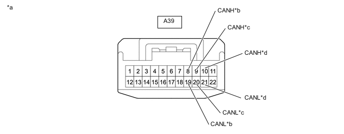
*a Front view of wire harness connector
(to No. 1 CAN Junction Connector)
*b to Millimeter Wave Radar Sensor Assembly (w/ Pre-crash Safety System) *c to No. 5 CAN Junction Connector *d to No. 8 CAN Junction Connector No. 1 CAN Junction Connector Wiring Color Connect to A39-8 (CANH) L Millimeter wave radar sensor assembly* A39-19 (CANL) LG A39-9 (CANH) L No. 5 CAN junction connector A39-20 (CANL) LG A39-10 (CANH) V No. 8 CAN junction connector A39-21 (CANL) LG
-
*: w/ Pre-crash Safety System
-
-
No. 2 CAN Junction Connector
Tech Tips
Connectors that connect to the CAN junction connector can be distinguished by color of their CAN bus lines. When the connectors have been disconnected from the CAN junction connector, reconnecting the connectors to non-original positions on the CAN junction connector does not affect system performance. However, it is preferred to reconnect the connectors to their original positions to avoid negative effects on the wiring such as tension on the wiring harnesses, and to make future maintenance easier.
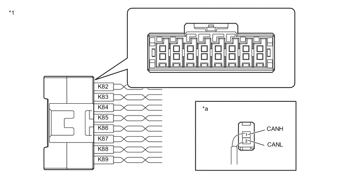
*1 No. 2 CAN Junction Connector - - *a Rear view of wire harness connector
(to No. 2 CAN Junction Connector)
- - No. 2 CAN Junction Connector Wiring Color Connect to K82-1 (CANH) B No. 3 CAN junction connector K82-2 (CANL) W K83-1 (CANH) R Spiral cable with sensor sub-assembly (steering angle sensor) K83-2 (CANL) W K84-1 (CANH) G No. 9 CAN junction connector K84-2 (CANL) W K85-1 (CANH) L Brake actuator assembly (skid control ECU) K85-2 (CANL) W K86-1 (CANH) Y Air conditioning amplifier assembly K86-2 (CANL) W K87-1 (CANH) V Yaw rate and acceleration sensor (yaw rate sensor) K87-2 (CANL) W K88-1 (CANH) P Headlight light control ECU sub-assembly LH K88-2 (CANL) W K89-1 (CANH) BE Main body ECU (multiplex network body ECU) K89-2 (CANL) W -
No. 3 CAN Junction Connector
Tech Tips
Connectors that connect to the CAN junction connector can be distinguished by color of their CAN bus lines. When the connectors have been disconnected from the CAN junction connector, reconnecting the connectors to non-original positions on the CAN junction connector does not affect system performance. However, it is preferred to reconnect the connectors to their original positions to avoid negative effects on the wiring such as tension on the wiring harnesses, and to make future maintenance easier.

*1 No. 3 CAN Junction Connector - - *a Rear view of wire harness connector
(to No. 3 CAN Junction Connector)
- - No. 3 CAN Junction Connector Wiring Color Connect to K90-1 (CANH) B No. 2 CAN junction connector K90-2 (CANL) W K91-1 (CANH) R Stereo component equalizer assembly K91-2 (CANL) W K92-1 (CANH) G Central gateway ECU (network gateway ECU) K92-2 (CANL) W K93-1 (CANH) L Power steering ECU assembly K93-2 (CANL) W K94-1 (CANH) Y Airbag ECU assembly K94-2 (CANL) W K95-1 (CANH) V Combination meter mirror ECU* K95-2 (CANL) W K96-1 (CANH) P Certification ECU (smart key ECU assembly) K96-2 (CANL) W K97-1 (CANH) BE Combination meter assembly K97-2 (CANL) W
-
*: w/ Headup Display
-
-
No. 4 CAN Junction Connector
*a Front view of wire harness connector
(to No. 4 CAN Junction Connector)
*b to Front Multiplex Network Door ECU LH *c to No. 10 CAN Junction Connector *d to Position Control ECU and Switch Assembly LH *e to Multiplex Tilt and Telescopic ECU *f to No. 7 CAN Junction Connector No. 4 CAN Junction Connector Wiring Color Connect to K105-7 (CANH) Y Front multiplex network door ECU LH K105-18 (CANL) GR K105-8 (CANH) L No. 10 CAN junction connector K105-19 (CANL) GR K105-9 (CANH) G Position control ECU and switch assembly LH K105-20 (CANL) GR K105-10 (CANH) R Multiplex tilt and telescopic ECU K105-21 (CANL) GR K105-11 (CANH) B No. 7 CAN junction connector K105-22 (CANL) GR -
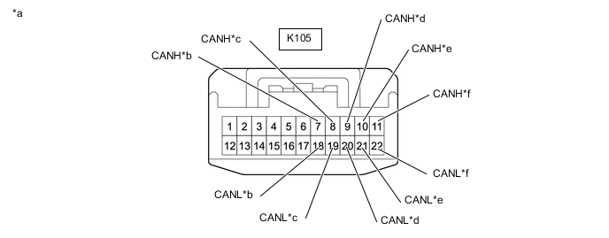
No. 5 CAN Junction Connector
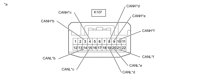
*a Front view of wire harness connector
(to No. 5 CAN Junction Connector)
*b to No. 13 Junction Connector *c to No. 1 CAN Junction Connector *d to Driving Support ECU Assembly (w/ Pre-crash Safety System) *e to Clearance Warning ECU Assembly (w/ LEXUS Parking Assist-sensor System) *f to Forward Recognition Camera (w/ Pre-crash Safety System) No. 5 CAN Junction Connector Wiring Color Connect to K107-3 (CANH) L No. 13 junction connector K107-14 (CANL) LG K107-4 (CANH) L No. 1 CAN junction connector K107-15 (CANL) LG K107-8 (CANH) L Driving support ECU assembly*1 K107-19 (CANL) LG K107-9 (CANH) L Clearance warning ECU assembly*2 K107-20 (CANL) LG K107-10 (CANH) L Forward recognition camera*1 K107-21 (CANL) LG
-
*1: w/ Pre-crash Safety System
-
*2: w/ LEXUS Parking Assist-sensor System
-
-
No. 6 CAN Junction Connector
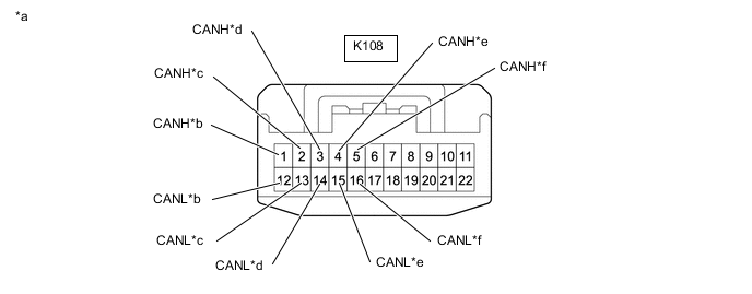
*a Front view of wire harness connector
(to No. 6 CAN Junction Connector)
*b to Driving Support ECU Assembly (w/ Pre-crash Safety System) *c to No. 10 CAN Junction Connector *d to Brake Actuator Assembly (Skid Control ECU) *e to Roll Rate and Vertical Acceleration Sensor (Yaw Rate Sensor) *f No. 7 CAN Junction Connector No. 6 CAN Junction Connector Wiring Color Connect to K108-1 (CANH) G Driving support ECU assembly* K108-12 (CANL) SB K108-2 (CANH) R No. 10 CAN junction connector K108-13 (CANL) SB K108-3 (CANH) Y Brake actuator assembly (skid control ECU) K108-14 (CANL) SB K108-4 (CANH) V Roll rate and vertical acceleration sensor (yaw rate sensor) K108-15 (CANL) SB K108-5 (CANH) B No. 7 CAN junction connector K108-16 (CANL) SB
-
*: w/ Pre-crash Safety System
-
-
No. 7 CAN Junction Connector
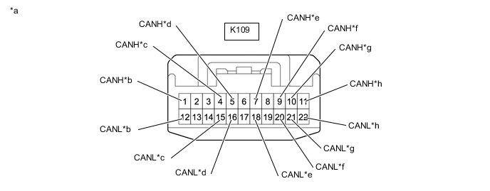
*a Front view of wire harness connector
(to No. 7 CAN Junction Connector)
*b to ECM *c to Central Gateway ECU (Network Gateway ECU) *d to No. 6 CAN Junction Connector *e to No. 4 CAN Junction Connector *f to Position Control ECU and Switch Assembly RH *g to No. 1 CAN Junction Terminal *h to Front Multiplex Network Door ECU RH No. 7 CAN Junction Connector Wiring Color Connect to K109-1 (CANH) P ECM K109-12 (CANL) SB K109-4 (CANH) V Central gateway ECU (network gateway ECU) K109-15 (CANL) SB K109-5 (CANH) B No. 6 CAN junction connector K109-16 (CANL) SB K109-7 (CANH) B No. 4 CAN junction connector K109-18 (CANL) GR K109-9 (CANH) G Position control ECU and switch assembly RH K109-20 (CANL) GR K109-10 (CANH) L No. 1 CAN junction terminal K109-21 (CANL) GR K109-11 (CANH) Y Front multiplex network door ECU RH K109-22 (CANL) GR -
No. 8 CAN Junction Connector
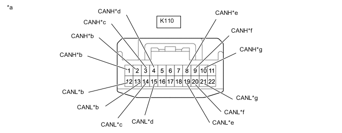
*a Front view of wire harness connector
(to No. 8 CAN Junction Connector)
*b to Central Gateway ECU (Network Gateway ECU) *c to Telematics Transceiver (w/ Telematics Transceiver) *d to Radio Receiver Assembly *e to Central Gateway ECU (Network Gateway ECU) *f to Absorber Control ECU *g to No. 1 CAN Junction Connector - - No. 8 CAN Junction Connector Wiring Color Connect to K110-1 (CANH) B Central gateway ECU (network gateway ECU) K110-12 (CANL) W K110-2 (CANH) B Central gateway ECU (network gateway ECU) K110-13 (CANL) W K110-3 (CANH) B Telematics transceiver* K110-14 (CANL) W K110-4 (CANH) B Radio receiver assembly K110-15 (CANL) W K110-8 (CANH) V Central gateway ECU (network gateway ECU) K110-19 (CANL) LG K110-9 (CANH) V Absorber control ECU K110-20 (CANL) LG K110-10 (CANH) V No. 1 CAN junction connector K110-21 (CANL) LG
-
*: w/ Telematics Transceiver
-
-
No. 9 CAN Junction Connector
Tech Tips
Connectors that connect to the CAN junction connector can be distinguished by color of their CAN bus lines. When the connectors have been disconnected from the CAN junction connector, reconnecting the connectors to non-original positions on the CAN junction connector does not affect system performance. However, it is preferred to reconnect the connectors to their original positions to avoid negative effects on the wiring such as tension on the wiring harnesses, and to make future maintenance easier.
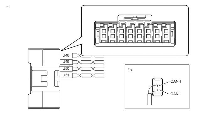
*1 No. 9 CAN Junction Connector - - *a Rear view of wire harness connector
(to No. 9 CAN Junction Connector)
- - No. 9 CAN Junction Connector Wiring Color Connect to U48-1 (CANH) B Parking brake ECU assembly U48-2 (CANL) W U49-1 (CANH) R ECM U49-2 (CANL) W U50-1 (CANH) G No. 2 CAN junction connector U50-2 (CANL) W U51-1 (CANH) L Torque vectoring differential ECU assembly U51-2 (CANL) W -
No. 10 CAN Junction Connector
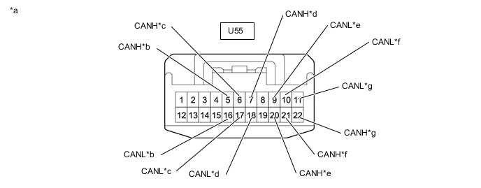
*a Front view of wire harness connector
(to No. 10 CAN Junction Connector)
*b to No. 2 CAN Junction Terminal *c to No. 6 CAN Junction Connector *d to Torque Vectoring Differential ECU Assembly *e to Main Body ECU (Multiplex Network Body ECU) *f to No. 4 CAN Junction Connector *g
-
to Luggage Closer Motor Assembly (w/ Power Trunk Lid System)
-
to Multiplex Network Door ECU (w/o Power Trunk Lid System)
- - No. 10 CAN Junction Connector Wiring Color Connect to U55-5 (CANH) B No. 2 CAN junction terminal U55-16 (CANL) SB U55-6 (CANH) R No. 6 CAN junction connector U55-17 (CANL) SB U55-7 (CANH) G Torque vectoring differential ECU assembly U55-18 (CANL) SB U55-20 (CANH) R Main body ECU (multiplex network body ECU) U55-9 (CANL) GR U55-21 (CANH) L No. 4 CAN junction connector U55-10 (CANL) GR U55-22 (CANH) G
-
Luggage closer motor assembly*1
-
Multiplex network door ECU*2
U55-11 (CANL) GR
-
*1: w/ Power Trunk Lid System
-
*2: w/o Power Trunk Lid System
-
-
No. 13 Junction Connector
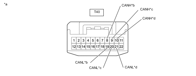
*a Front view of wire harness connector
(to No. 13 Junction Connector)
*b to No. 5 CAN Junction Connector *c to Central Gateway ECU (Network Gateway ECU) *d to Blind Spot Monitor Sensor RH (w/ Blind Spot Monitor System) No. 13 Junction Connector Wiring Color Connect to T40-8 (CANH) L No. 5 CAN junction connector T40-19 (CANL) LG T40-9 (CANH) P Central gateway ECU (network gateway ECU) T40-20 (CANL) LG T40-10 (CANH) L Blind spot monitor sensor RH* T40-21 (CANL) LG
-
*: w/ Blind Spot Monitor System
-
-
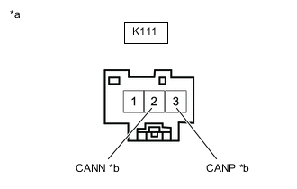
*a Front view of wire harness connector
(to No. 1 CAN Junction Terminal)
*b for No. 7 CAN Junction Connector No. 1 CAN Junction Terminal
No. 1 CAN Junction Terminal Wiring Color Connect to K111-2 (CANN) GR No. 7 CAN junction connector K111-3 (CANP) L -

*a Front view of wire harness connector
(to No. 2 CAN Junction Terminal)
*b for No. 10 CAN Junction Connector No. 2 CAN Junction Terminal
No. 2 CAN Junction Terminal Wiring Color Connect to U57-2 (CANL) SB No. 10 CAN junction connector U57-3 (CANH) B
-
-
CHECK DLC3
-
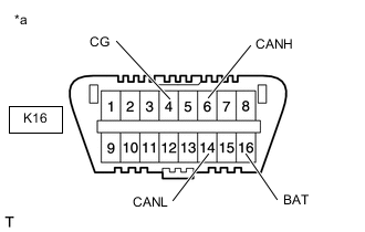
*a Front view of DLC3 Disconnect the cable from the negative (-) battery terminal before measuring the resistances of the CAN main wire and CAN branch wire.
CAUTION:
Wait at least 90 seconds after disconnecting the cable from the negative (-) battery terminal to disable the SRS system.
Note
-
After turning the engine switch off, waiting time may be required before disconnecting the cable from the negative (-) battery terminal. Therefore, make sure to read the disconnecting the cable from the battery terminal notice before proceeding with work.
-
When disconnecting the cable, some systems need to be initialized after the cable is reconnected.
-
-
Measure the resistance according to the value(s) in the table below.
Terminal No. (Symbol) Wiring Color Terminal Description Condition Specified Condition K16-6 (CANH) - K16-14 (CANL) P - V HIGH-level CAN bus wire - LOW-level CAN bus wire Cable disconnected from negative (-) battery terminal 54 to 66 Ω K16-6 (CANH) - K16-4 (CG) P - W-B HIGH-level CAN bus wire - GND Cable disconnected from negative (-) battery terminal 200 Ω or higher K16-14 (CANL) - K16-4 (CG) V - W-B LOW-level CAN bus wire - GND Cable disconnected from negative (-) battery terminal 200 Ω or higher K16-6 (CANH) - K16-16 (BAT) P - W HIGH-level CAN bus wire - Battery positive (+) Cable disconnected from negative (-) battery terminal 6 kΩ or higher K16-14 (CANL) - K16-16 (BAT) V - W LOW-level CAN bus wire - Battery positive (+) Cable disconnected from negative (-) battery terminal 6 kΩ or higher
-
-
CHECK CENTRAL GATEWAY ECU (NETWORK GATEWAY ECU)
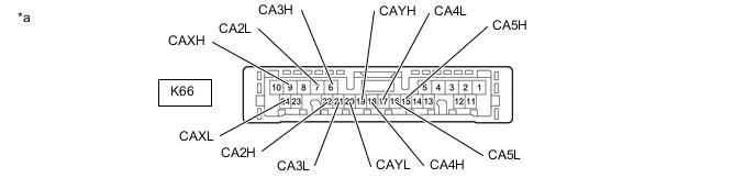
*a Component without harness connected
(Central Gateway ECU (Network Gateway ECU))
- -
-
Disconnect the central gateway ECU (network gateway ECU) connector.
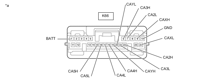
*a Front view of wire harness connector
(to Central Gateway ECU (Network Gateway ECU))
- - -
Measure the resistance according to the value(s) in the table below.
Bus 2 Terminal No. (Symbol) Wiring Color Terminal Description Condition Specified Condition K66-18 (CA4H) - K66-17 (CA4L) G - W HIGH-level CAN bus wire - LOW-level CAN bus wire Cable disconnected from negative (-) battery terminal 54 to 69 Ω K66-18 (CA4H) - K66-10 (GND) G - W-B HIGH-level CAN bus wire - GND Cable disconnected from negative (-) battery terminal 200 Ω or higher K66-17 (CA4L) - K66-10 (GND) W - W-B LOW-level CAN bus wire - GND Cable disconnected from negative (-) battery terminal 200 Ω or higher K66-18 (CA4H) - K66-1 (BATT) G - GR HIGH-level CAN bus wire - Battery positive (+) Cable disconnected from negative (-) battery terminal 6 kΩ or higher K66-17 (CA4L) - K66-1 (BATT) W - GR LOW-level CAN bus wire - Battery positive (+) Cable disconnected from negative (-) battery terminal 6 kΩ or higher Bus 3 Terminal No. (Symbol) Wiring Color Terminal Description Condition Specified Condition K66-6 (CA3H) - K66-19 (CAYH) B - B HIGH-level CAN bus wire - HIGH-level CAN bus wire Cable disconnected from negative (-) battery terminal Below 1 Ω K66-21 (CA3L) - K66-20 (CAYL) W - W LOW-level CAN bus wire - LOW-level CAN bus wire Cable disconnected from negative (-) battery terminal Below 1 Ω K66-6 (CA3H) - K66-21 (CA3L) B - W HIGH-level CAN bus wire - LOW-level CAN bus wire Cable disconnected from negative (-) battery terminal 200 Ω or higher K66-6 (CA3H) - K66-10 (GND) B - W-B HIGH-level CAN bus wire - GND Cable disconnected from negative (-) battery terminal 200 Ω or higher K66-21 (CA3L) - K66-10 (GND) W - W-B LOW-level CAN bus wire - GND Cable disconnected from negative (-) battery terminal 200 Ω or higher K66-6 (CA3H) - K66-1 (BATT) B - GR HIGH-level CAN bus wire - Battery positive (+) Cable disconnected from negative (-) battery terminal 6 kΩ or higher K66-21 (CA3L) - K66-1 (BATT) W - GR LOW-level CAN bus wire - Battery positive (+) Cable disconnected from negative (-) battery terminal 6 kΩ or higher K66-19 (CAYH) - K66-20 (CAYL) B - W HIGH-level CAN bus wire - LOW-level CAN bus wire Cable disconnected from negative (-) battery terminal 200 Ω or higher K66-19 (CAYH) - K66-10 (GND) B - W-B HIGH-level CAN bus wire - GND Cable disconnected from negative (-) battery terminal 200 Ω or higher K66-20 (CAYL) - K66-10 (GND) W - W-B LOW-level CAN bus wire - GND Cable disconnected from negative (-) battery terminal 200 Ω or higher K66-19 (CAYH) - K66-1 (BATT) B - GR HIGH-level CAN bus wire - Battery positive (+) Cable disconnected from negative (-) battery terminal 6 kΩ or higher K66-20 (CAYL) - K66-1 (BATT) W - GR LOW-level CAN bus wire - Battery positive (+) Cable disconnected from negative (-) battery terminal 6 kΩ or higher Bus 4 Terminal No. (Symbol) Wiring Color Terminal Description Condition Specified Condition K66-22 (CA2H) - K66-7 (CA2L) V - SB HIGH-level CAN bus wire - LOW-level CAN bus wire Cable disconnected from negative (-) battery terminal 54 to 69 Ω K66-22 (CA2H) - K66-10 (GND) V - W-B HIGH-level CAN bus wire - GND Cable disconnected from negative (-) battery terminal 200 Ω or higher K66-7 (CA2L) - K66-10 (GND) SB - W-B LOW-level CAN bus wire - GND Cable disconnected from negative (-) battery terminal 200 Ω or higher K66-22 (CA2H) - K66-1 (BATT) V - GR HIGH-level CAN bus wire - Battery positive (+) Cable disconnected from negative (-) battery terminal 6 kΩ or higher K66-7 (CA2L) - K66-1 (BATT) SB - GR LOW-level CAN bus wire - Battery positive (+) Cable disconnected from negative (-) battery terminal 6 kΩ or higher Bus 5 Terminal No. (Symbol) Wiring Color Terminal Description Condition Specified Condition K66-15 (CA5H) - K66-9 (CAXH) V - P HIGH-level CAN bus wire - HIGH-level CAN bus wire Cable disconnected from negative (-) battery terminal Below 1 Ω K66-16 (CA5L) - K66-24 (CAXL) LG - LG LOW-level CAN bus wire - LOW-level CAN bus wire Cable disconnected from negative (-) battery terminal Below 1 Ω K66-15 (CA5H) - K66-16 (CA5L) V - LG HIGH-level CAN bus wire - LOW-level CAN bus wire Cable disconnected from negative (-) battery terminal 200 Ω or higher K66-15 (CA5H) - K66-10 (GND) V - W-B HIGH-level CAN bus wire - GND Cable disconnected from negative (-) battery terminal 200 Ω or higher K66-16 (CA5L) - K66-10 (GND) LG - W-B LOW-level CAN bus wire - GND Cable disconnected from negative (-) battery terminal 200 Ω or higher K66-15 (CA5H) - K66-1 (BATT) V - GR HIGH-level CAN bus wire - Battery positive (+) Cable disconnected from negative (-) battery terminal 6 kΩ or higher K66-16 (CA5L) - K66-1 (BATT) LG - GR LOW-level CAN bus wire - Battery positive (+) Cable disconnected from negative (-) battery terminal 6 kΩ or higher K66-9 (CAXH) - K66-24 (CAXL) P - LG HIGH-level CAN bus wire - LOW-level CAN bus wire Cable disconnected from negative (-) battery terminal 200 Ω or higher K66-9 (CAXH) - K66-10 (GND) P - W-B HIGH-level CAN bus wire - GND Cable disconnected from negative (-) battery terminal 200 Ω or higher K66-24 (CAXL) - K66-10 (GND) LG - W-B LOW-level CAN bus wire - GND Cable disconnected from negative (-) battery terminal 200 Ω or higher K66-9 (CAXH) - K66-1 (BATT) P - GR HIGH-level CAN bus wire - Battery positive (+) Cable disconnected from negative (-) battery terminal 6 kΩ or higher K66-24 (CAXL) - K66-1 (BATT) LG - GR LOW-level CAN bus wire - Battery positive (+) Cable disconnected from negative (-) battery terminal 6 kΩ or higher
-
-
CHECK ECM
-
Refer to Terminals of ECU for SFI System for further details.
-
w/ Canister Pump Module: Click here
-
w/o Canister Pump Module: Click here
-
-
Disconnect the ECM connectors.
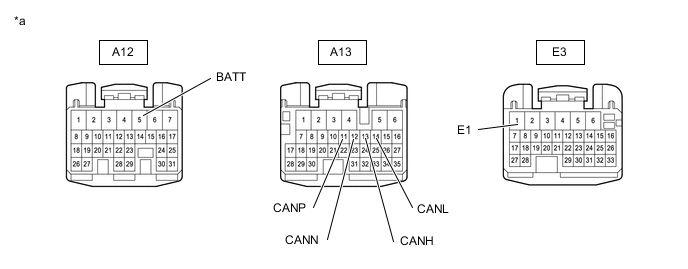
*a Front view of wire harness connector
(to ECM)
- - -
Measure the resistance according to the value(s) in the table below.
Bus 2 Terminal No. (Symbol) Wiring Color Terminal Description Condition Specified Condition A13-13 (CANH) - A13-14 (CANL) R - W HIGH-level CAN bus wire - LOW-level CAN bus wire Cable disconnected from negative (-) battery terminal 108 to 132 Ω A13-13 (CANH) - E3-1 (E1) R - W-B HIGH-level CAN bus wire - GND Cable disconnected from negative (-) battery terminal 200 Ω or higher A13-14 (CANL) - E3-1 (E1) W - W-B LOW-level CAN bus wire - GND Cable disconnected from negative (-) battery terminal 200 Ω or higher A13-13 (CANH) - A12-5 (BATT) R - L HIGH-level CAN bus wire - Battery positive (+) Cable disconnected from negative (-) battery terminal 6 kΩ or higher A13-14 (CANL) - A12-5 (BATT) W - L LOW-level CAN bus wire - Battery positive (+) Cable disconnected from negative (-) battery terminal 6 kΩ or higher Bus 4 Terminal No. (Symbol) Wiring Color Terminal Description Condition Specified Condition A13-11 (CANP) - A13-12 (CANN) P - SB HIGH-level CAN bus wire - LOW-level CAN bus wire Cable disconnected from negative (-) battery terminal 108 to 132 Ω A13-11 (CANP) - E3-1 (E1) P - W-B HIGH-level CAN bus wire - GND Cable disconnected from negative (-) battery terminal 200 Ω or higher A13-12 (CANN) - E3-1 (E1) SB - W-B LOW-level CAN bus wire - GND Cable disconnected from negative (-) battery terminal 200 Ω or higher A13-11 (CANP) - A12-5 (BATT) P - L HIGH-level CAN bus wire - Battery positive (+) Cable disconnected from negative (-) battery terminal 6 kΩ or higher A13-12 (CANN) - A12-5 (BATT) SB - L LOW-level CAN bus wire - Battery positive (+) Cable disconnected from negative (-) battery terminal 6 kΩ or higher
-
-
CHECK MAIN BODY ECU (MULTIPLEX NETWORK BODY ECU) AND COWL SIDE JUNCTION BLOCK LH
-
Refer to Terminals of ECU for Lighting System for further details.
-
Remove the main body ECU (multiplex network body ECU).
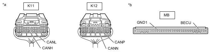
*a Rear view of wire harness connector
(to Main Body ECU (Multiplex Network Body ECU))
*b Front view of wire harness connector
(to Main Body ECU (Multiplex Network Body ECU))
-
Reconnect the cowl side junction block LH connectors.
-
Measure the resistance according to the value(s) in the table below.
Bus 2 Terminal No. (Symbol) Wiring Color Terminal Description Condition Specified Condition K11-14 (CANH) - K11-13 (CANL) BE - W HIGH-level CAN bus wire - LOW-level CAN bus wire Cable disconnected from negative (-) battery terminal 54 to 69 Ω K11-14 (CANH) - MB-11 (GND1) BE - None HIGH-level CAN bus wire - GND Cable disconnected from negative (-) battery terminal 200 Ω or higher K11-13 (CANL) - MB-11 (GND1) W - None LOW-level CAN bus wire - GND Cable disconnected from negative (-) battery terminal 200 Ω or higher K11-14 (CANH) - MB-30 (BECU) BE - None HIGH-level CAN bus wire - Battery positive (+) Cable disconnected from negative (-) battery terminal 6 kΩ or higher K11-13 (CANL) - MB-30 (BECU) W - None LOW-level CAN bus wire - Battery positive (+) Cable disconnected from negative (-) battery terminal 6 kΩ or higher Sub Bus 1 Terminal No. (Symbol) Wiring Color Terminal Description Condition Specified Condition K12-9 (CANP) - K12-10 (CANN) R - GR HIGH-level CAN bus wire - LOW-level CAN bus wire Cable disconnected from negative (-) battery terminal 108 to 132 Ω K12-9 (CANP) - MB-11 (GND1) R - None HIGH-level CAN bus wire - GND Cable disconnected from negative (-) battery terminal 200 Ω or higher K12-10 (CANN) - MB-11 (GND1) GR - None LOW-level CAN bus wire - GND Cable disconnected from negative (-) battery terminal 200 Ω or higher K12-9 (CANP) - MB-30 (BECU) R - None HIGH-level CAN bus wire - Battery positive (+) Cable disconnected from negative (-) battery terminal 6 kΩ or higher K12-10 (CANN) - MB-30 (BECU) GR - None LOW-level CAN bus wire - Battery positive (+) Cable disconnected from negative (-) battery terminal 6 kΩ or higher
-
-
CHECK CERTIFICATION ECU (SMART KEY ECU ASSEMBLY)
-
Refer to Terminals of ECU for Entry and Start System with Push-button Start (for Entry Function) for further details.
-
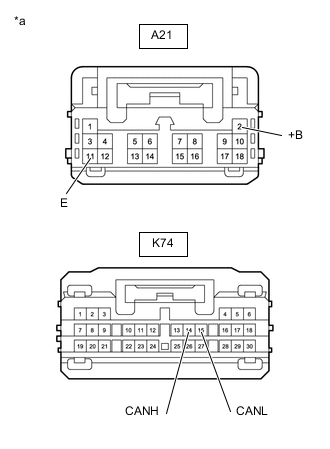
*a Front view of wire harness connector
(to Certification ECU (Smart Key ECU Assembly))
Disconnect the certification ECU (smart key ECU assembly) connectors.
-
Measure the resistance according to the value(s) in the table below.
Terminal No. (Symbol) Wiring Color Terminal Description Condition Specified Condition K74-14 (CANH) - K74-15 (CANL) P - W HIGH-level CAN bus wire - LOW-level CAN bus wire Cable disconnected from negative (-) battery terminal 54 to 69 Ω K74-14 (CANH) - A21-11 (E) P - W-B HIGH-level CAN bus wire - GND Cable disconnected from negative (-) battery terminal 200 Ω or higher K74-15 (CANL) - A21-11 (E) W - W-B LOW-level CAN bus wire - GND Cable disconnected from negative (-) battery terminal 200 Ω or higher K74-14 (CANH) - A21-2 (+B) P - W HIGH-level CAN bus wire - Battery positive (+) Cable disconnected from negative (-) battery terminal 6 kΩ or higher K74-15 (CANL) - A21-2 (+B) W - W LOW-level CAN bus wire - Battery positive (+) Cable disconnected from negative (-) battery terminal 6 kΩ or higher
-
-
CHECK POWER STEERING ECU ASSEMBLY
-
Refer to Terminals of ECU for Power Steering System for further details.
-
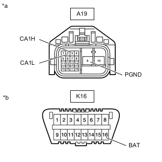
*a Front view of wire harness connector
(to Power Steering ECU Assembly)
*b Front view of DLC3 Disconnect the power steering ECU assembly connector.
-
Measure the resistance according to the value(s) in the table below.
Terminal No. (Symbol) Wiring Color Terminal Description Condition Specified Condition A19-3 (CA1H) - A19-2 (CA1L) L - W HIGH-level CAN bus wire - LOW-level CAN bus wire Cable disconnected from negative (-) battery terminal 54 to 69 Ω A19-3 (CA1H) - A19-9 (PGND) L - B HIGH-level CAN bus wire - GND Cable disconnected from negative (-) battery terminal 200 Ω or higher A19-2 (CA1L) - A19-9 (PGND) W - B LOW-level CAN bus wire - GND Cable disconnected from negative (-) battery terminal 200 Ω or higher A19-3 (CA1H) - K16-16 (BAT) L - W HIGH-level CAN bus wire - Battery positive (+) Cable disconnected from negative (-) battery terminal 6 kΩ or higher A19-2 (CA1L) - K16-16 (BAT) W - W LOW-level CAN bus wire - Battery positive (+) Cable disconnected from negative (-) battery terminal 6 kΩ or higher
-
-
CHECK TORQUE VECTORING DIFFERENTIAL ECU ASSEMBLY
-
Refer to Terminals of ECU for Torque Vectoring Differential System for further details.
-
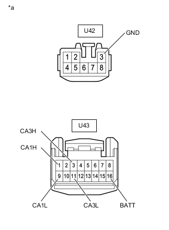
*a Front view of wire harness connector
(to Torque Vectoring Differential ECU Assembly)
Disconnect the torque vectoring differential ECU assembly connectors.
-
Measure the resistance according to the value(s) in the table below.
Bus 2 Terminal No. (Symbol) Wiring Color Terminal Description Condition Specified Condition U43-1 (CA1H) - U43-9 (CA1L) L - W HIGH-level CAN bus wire - LOW-level CAN bus wire Cable disconnected from negative (-) battery terminal 54 to 69 Ω U43-1 (CA1H) - U42-3 (GND) L - W-B HIGH-level CAN bus wire - GND Cable disconnected from negative (-) battery terminal 200 Ω or higher U43-9 (CA1L) - U42-3 (GND) W - W-B LOW-level CAN bus wire - GND Cable disconnected from negative (-) battery terminal 200 Ω or higher U43-1 (CA1H) - U43-16 (BATT) L - LG HIGH-level CAN bus wire - Battery positive (+) Cable disconnected from negative (-) battery terminal 6 kΩ or higher U43-9 (CA1L) - U43-16 (BATT) W - LG LOW-level CAN bus wire - Battery positive (+) Cable disconnected from negative (-) battery terminal 6 kΩ or higher Bus 4 Terminal No. (Symbol) Wiring Color Terminal Description Condition Specified Condition U43-3 (CA3H) - U43-11 (CA3L) G - SB HIGH-level CAN bus wire - LOW-level CAN bus wire Cable disconnected from negative (-) battery terminal 54 to 69 Ω U43-3 (CA3H) - U42-3 (GND) G - W-B HIGH-level CAN bus wire - GND Cable disconnected from negative (-) battery terminal 200 Ω or higher U43-11 (CA3L) - U42-3 (GND) SB - W-B LOW-level CAN bus wire - GND Cable disconnected from negative (-) battery terminal 200 Ω or higher U43-3 (CA3H) - U43-16 (BATT) G - LG HIGH-level CAN bus wire - Battery positive (+) Cable disconnected from negative (-) battery terminal 6 kΩ or higher U43-11 (CA3L) - U43-16 (BATT) SB - LG LOW-level CAN bus wire - Battery positive (+) Cable disconnected from negative (-) battery terminal 6 kΩ or higher
-
-
CHECK BRAKE ACTUATOR ASSEMBLY (SKID CONTROL ECU)
-
Refer to Terminals of ECU for Vehicle Stability Control System for further details.
-
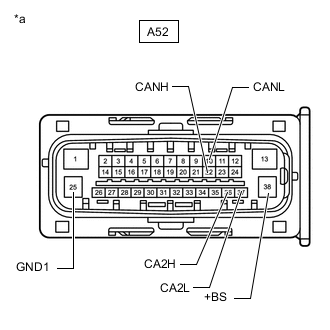
*a Front view of wire harness connector
(to Brake Actuator Assembly (skid control ECU))
Disconnect the brake actuator assembly (skid control ECU) connector.
-
Measure the resistance according to the value(s) in the table below.
Bus 2 Terminal No. (Symbol) Wiring Color Terminal Description Condition Specified Condition A52-22 (CANH) - A52-10 (CANL) L - W HIGH-level CAN bus wire - LOW-level CAN bus wire Cable disconnected from negative (-) battery terminal 54 to 69 Ω A52-22 (CANH) - A52-25 (GND1) L - W-B HIGH-level CAN bus wire - GND Cable disconnected from negative (-) battery terminal 200 Ω or higher A52-10 (CANL) - A52-25 (GND1) W - W-B LOW-level CAN bus wire - GND Cable disconnected from negative (-) battery terminal 200 Ω or higher A52-22 (CANH) - A52-38 (+BS) L - R HIGH-level CAN bus wire - Battery positive (+) Cable disconnected from negative (-) battery terminal 6 kΩ or higher A52-10 (CANL) - A52-38 (+BS) W - R LOW-level CAN bus wire - Battery positive (+) Cable disconnected from negative (-) battery terminal 6 kΩ or higher Bus 4 Terminal No. (Symbol) Wiring Color Terminal Description Condition Specified Condition A52-36 (CA2H) - A52-37 (CA2L) Y - SB HIGH-level CAN bus wire - LOW-level CAN bus wire Cable disconnected from negative (-) battery terminal 54 to 69 Ω A52-36 (CA2H) - A52-25 (GND1) Y - W-B HIGH-level CAN bus wire - GND Cable disconnected from negative (-) battery terminal 200 Ω or higher A52-37 (CA2L) - A52-25 (GND1) SB - W-B LOW-level CAN bus wire - GND Cable disconnected from negative (-) battery terminal 200 Ω or higher A52-36 (CA2H) - A52-38 (+BS) Y - R HIGH-level CAN bus wire - Battery positive (+) Cable disconnected from negative (-) battery terminal 6 kΩ or higher A52-37 (CA2L) - A52-38 (+BS) SB - R LOW-level CAN bus wire - Battery positive (+) Cable disconnected from negative (-) battery terminal 6 kΩ or higher
-
-
CHECK AIRBAG ECU ASSEMBLY
-
Refer to Terminals of ECU for Airbag System for further details.
-
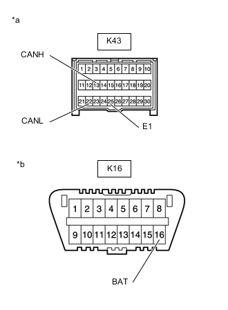
*a Front view of wire harness connector
(to Airbag ECU Assembly)
*b Front view of DLC3 Disconnect the airbag ECU assembly connector.
-
Measure the resistance according to the value(s) in the table below.
Terminal No. (Symbol) Wiring Color Terminal Description Condition Specified Condition K43-13 (CANH) - K43-22 (CANL) Y - W HIGH-level CAN bus wire - LOW-level CAN bus wire Cable disconnected from negative (-) battery terminal 54 to 69 Ω K43-13 (CANH) - K43-25 (E1) Y - W-B HIGH-level CAN bus wire - GND Cable disconnected from negative (-) battery terminal 200 Ω or higher K43-22 (CANL) - K43-25 (E1) W - W-B LOW-level CAN bus wire - GND Cable disconnected from negative (-) battery terminal 200 Ω or higher K43-13 (CANH) - K16-16 (BAT) Y - W HIGH-level CAN bus wire - Battery positive (+) Cable disconnected from negative (-) battery terminal 6 kΩ or higher K43-22 (CANL) - K16-16 (BAT) W - W LOW-level CAN bus wire - Battery positive (+) Cable disconnected from negative (-) battery terminal 6 kΩ or higher
-
-
CHECK SPIRAL CABLE WITH SENSOR SUB-ASSEMBLY (STEERING ANGLE SENSOR)

-
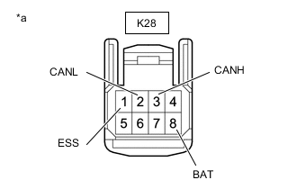
*a Front view of wire harness connector
(to Spiral Cable with Sensor Sub-assembly (Steering Angle Sensor))
Disconnect the spiral cable with sensor sub-assembly (steering angle sensor) connector.
-
Measure the resistance according to the value(s) in the table below.
Terminal No. (Symbol) Wiring Color Terminal Description Condition Specified Condition K28-3 (CANH) - K28-2 (CANL) R - W HIGH-level CAN bus wire - LOW-level CAN bus wire Cable disconnected from negative (-) battery terminal 54 to 69 Ω K28-3 (CANH) - K28-1 (ESS) R - W-B HIGH-level CAN bus wire - GND Cable disconnected from negative (-) battery terminal 200 Ω or higher K28-2 (CANL) - K28-1 (ESS) W - W-B LOW-level CAN bus wire - GND Cable disconnected from negative (-) battery terminal 200 Ω or higher K28-3 (CANH) - K28-8 (BAT) R - GR HIGH-level CAN bus wire - Battery positive (+) Cable disconnected from negative (-) battery terminal 6 kΩ or higher K28-2 (CANL) - K28-8 (BAT) W - GR LOW-level CAN bus wire - Battery positive (+) Cable disconnected from negative (-) battery terminal 6 kΩ or higher
-
-
CHECK AIR CONDITIONING AMPLIFIER ASSEMBLY
-
Refer to Terminals of ECU for Air Conditioning System for further details.
-
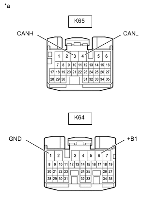
*a Front view of wire harness connector
(to Air Conditioning Amplifier Assembly)
Disconnect the air conditioning amplifier assembly connectors.
-
Measure the resistance according to the value(s) in the table below.
Terminal No. (Symbol) Wiring Color Terminal Description Condition Specified Condition K65-3 (CANH) - K65-4 (CANL) Y - W HIGH-level CAN bus wire - LOW-level CAN bus wire Cable disconnected from negative (-) battery terminal 54 to 69 Ω K65-3 (CANH) - K64-1 (GND) Y - W-B HIGH-level CAN bus wire - GND Cable disconnected from negative (-) battery terminal 200 Ω or higher K65-4 (CANL) - K64-1 (GND) W - W-B LOW-level CAN bus wire - GND Cable disconnected from negative (-) battery terminal 200 Ω or higher K65-3 (CANH) - K64-6 (+B1) Y - W HIGH-level CAN bus wire - Battery positive (+) Cable disconnected from negative (-) battery terminal 6 kΩ or higher K65-4 (CANL) - K64-6 (+B1) W - W LOW-level CAN bus wire - Battery positive (+) Cable disconnected from negative (-) battery terminal 6 kΩ or higher
-
-
CHECK RADIO RECEIVER ASSEMBLY
-
w/ Navigation System
-
Refer to Terminals of ECU for Navigation System for further details.
-
-
w/o Navigation System
-
Refer to Terminals of ECU for Audio and Visual System for further details.
-
for 12.3 Inch Display: Click here
-
for 8 Inch Display: Click here
-
-
-
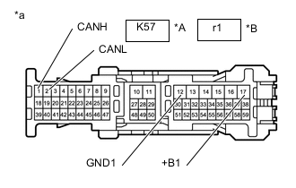
*A w/o Canister Pump Module *B w/ Canister Pump Module *a Front view of wire harness connector
(to Radio Receiver Assembly)
Disconnect the radio receiver assembly connector.
-
Measure the resistance according to the value(s) in the table below.
w/o Canister Pump Module Terminal No. (Symbol) Wiring Color Terminal Description Condition Specified Condition K57-1 (CANH) - K57-2 (CANL) B - W HIGH-level CAN bus wire - LOW-level CAN bus wire Cable disconnected from negative (-) battery terminal 54 to 69 Ω K57-1 (CANH) - K57-12 (GND1) B - W-B HIGH-level CAN bus wire - GND Cable disconnected from negative (-) battery terminal 200 Ω or higher K57-2 (CANL) - K57-12 (GND1) W - W-B LOW-level CAN bus wire - GND Cable disconnected from negative (-) battery terminal 200 Ω or higher K57-1 (CANH) - K57-17 (+B1) B - L HIGH-level CAN bus wire - Battery positive (+) Cable disconnected from negative (-) battery terminal 6 kΩ or higher K57-2 (CANL) - K57-17 (+B1) W - L LOW-level CAN bus wire - Battery positive (+) Cable disconnected from negative (-) battery terminal 6 kΩ or higher w/ Canister Pump Module Terminal No. (Symbol) Wiring Color Terminal Description Condition Specified Condition r1-1 (CANH) - r1-2 (CANL) LG - L HIGH-level CAN bus wire - LOW-level CAN bus wire Cable disconnected from negative (-) battery terminal 54 to 69 Ω r1-1 (CANH) - r1-12 (GND1) LG - W-B HIGH-level CAN bus wire - GND Cable disconnected from negative (-) battery terminal 200 Ω or higher r1-2 (CANL) - r1-12 (GND1) L - W-B LOW-level CAN bus wire - GND Cable disconnected from negative (-) battery terminal 200 Ω or higher r1-1 (CANH) - r1-17 (+B1) LG - BE HIGH-level CAN bus wire - Battery positive (+) Cable disconnected from negative (-) battery terminal 6 kΩ or higher r1-2 (CANL) - r1-17 (+B1) L - BE LOW-level CAN bus wire - Battery positive (+) Cable disconnected from negative (-) battery terminal 6 kΩ or higher
-
-
CHECK COMBINATION METER MIRROR ECU (w/ Headup Display)
-
Refer to Terminals of ECU for Headup Display System for further details.
-
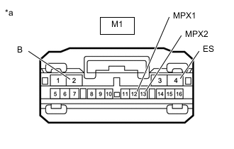
*a Front view of wire harness connector
(to Combination Meter Mirror ECU)
Disconnect the combination meter mirror ECU connector.
-
Measure the resistance according to the value(s) in the table below.
Terminal No. (Symbol) Wiring Color Terminal Description Condition Specified Condition M1-12 (MPX1) - M1-13 (MPX2) P - R HIGH-level CAN bus wire - LOW-level CAN bus wire Cable disconnected from negative (-) battery terminal 54 to 69 Ω M1-12 (MPX1) - M1-4 (ES) P - W-B HIGH-level CAN bus wire - GND Cable disconnected from negative (-) battery terminal 200 Ω or higher M1-13 (MPX2) - M1-4 (ES) R - W-B LOW-level CAN bus wire - GND Cable disconnected from negative (-) battery terminal 200 Ω or higher M1-12 (MPX1) - M1-2 (B) P - L HIGH-level CAN bus wire - Battery positive (+) Cable disconnected from negative (-) battery terminal 6 kΩ or higher M1-13 (MPX2) - M1-2 (B) R - L LOW-level CAN bus wire - Battery positive (+) Cable disconnected from negative (-) battery terminal 6 kΩ or higher
-
-
CHECK COMBINATION METER ASSEMBLY
-
Refer to Terminals of ECU for Meter / Gauge System for further details.
-
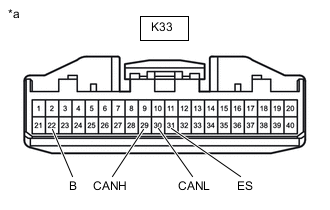
*a Front view of wire harness connector
(to Combination Meter Assembly)
Disconnect the combination meter assembly connector.
-
Measure the resistance according to the value(s) in the table below.
Terminal No. (Symbol) Wiring Color Terminal Description Condition Specified Condition K33-29 (CANH) - K33-30 (CANL) BE - W HIGH-level CAN bus wire - LOW-level CAN bus wire Cable disconnected from negative (-) battery terminal 108 to 132 Ω K33-29 (CANH) - K33-31 (ES) BE - W-B HIGH-level CAN bus wire - GND Cable disconnected from negative (-) battery terminal 200 Ω or higher K33-30 (CANL) - K33-31 (ES) W - W-B LOW-level CAN bus wire - GND Cable disconnected from negative (-) battery terminal 200 Ω or higher K33-29 (CANH) - K33-22 (B) BE - P HIGH-level CAN bus wire - Battery positive (+) Cable disconnected from negative (-) battery terminal 6 kΩ or higher K33-30 (CANL) - K33-22 (B) W - P LOW-level CAN bus wire - Battery positive (+) Cable disconnected from negative (-) battery terminal 6 kΩ or higher
-
-
CHECK PARKING BRAKE ECU ASSEMBLY
-
Refer to Terminals of ECU for Electric Parking Brake System for further details.
-
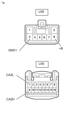
*a Front view of wire harness connector
(to Parking Brake ECU Assembly)
Disconnect the parking brake ECU assembly connectors.
-
Measure the resistance according to the value(s) in the table below.
Terminal No. (Symbol) Wiring Color Terminal Description Condition Specified Condition U30-9 (CA2H) - U30-1 (CA2L) B - W HIGH-level CAN bus wire - LOW-level CAN bus wire Cable disconnected from negative (-) battery terminal 54 to 69 Ω U30-9 (CA2H) - U29-3 (GND1) B - W-B HIGH-level CAN bus wire - GND Cable disconnected from negative (-) battery terminal 200 Ω or higher U30-1 (CA2L) - U29-3 (GND1) W - W-B LOW-level CAN bus wire - GND Cable disconnected from negative (-) battery terminal 200 Ω or higher U30-9 (CA2H) - U29-8 (+B) B - W HIGH-level CAN bus wire - Battery positive (+) Cable disconnected from negative (-) battery terminal 6 kΩ or higher U30-1 (CA2L) - U29-8 (+B) W - W LOW-level CAN bus wire - Battery positive (+) Cable disconnected from negative (-) battery terminal 6 kΩ or higher
-
-
CHECK ROLL RATE AND VERTICAL ACCELERATION SENSOR (YAW RATE SENSOR)

-
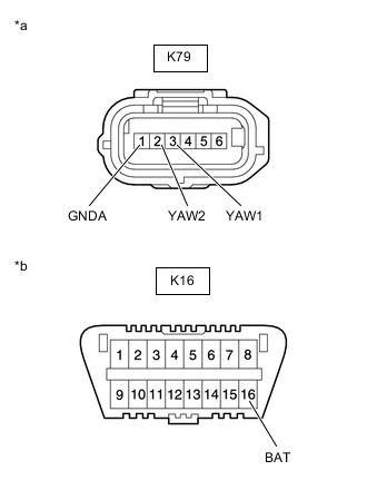
*a Front view of wire harness connector
(to Roll Rate and Vertical Acceleration Sensor (Yaw Rate Sensor))
*b Front view of DLC3 Disconnect the roll rate and vertical acceleration sensor (yaw rate sensor) connector.
-
Measure the resistance according to the value(s) in the table below.
Terminal No. (Symbol) Wiring Color Terminal Description Condition Specified Condition K79-3 (YAW1) - K79-2 (YAW2) V - SB HIGH-level CAN bus wire - LOW-level CAN bus wire Cable disconnected from negative (-) battery terminal 54 to 69 Ω K79-3 (YAW1) - K79-1 (GNDA) V - W-B HIGH-level CAN bus wire - GND Cable disconnected from negative (-) battery terminal 200 Ω or higher K79-2 (YAW2) - K79-1 (GNDA) SB - W-B LOW-level CAN bus wire - GND Cable disconnected from negative (-) battery terminal 200 Ω or higher K79-3 (YAW1) - K16-16 (BAT) V - W HIGH-level CAN bus wire - Battery positive (+) Cable disconnected from negative (-) battery terminal 6 kΩ or higher K79-2 (YAW2) - K16-16 (BAT) SB - W LOW-level CAN bus wire - Battery positive (+) Cable disconnected from negative (-) battery terminal 6 kΩ or higher
-
-
CHECK STEREO COMPONENT EQUALIZER ASSEMBLY
-
Refer to Terminals of ECU for ASC System for further details.
-
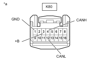
*a Front view of wire harness connector
(to Stereo Component Equalizer Assembly)
Disconnect the stereo component equalizer assembly connector.
-
Measure the resistance according to the value(s) in the table below.
Terminal No. (Symbol) Wiring Color Terminal Description Condition Specified Condition K80-4 (CANH) - K80-12 (CANL) R - W HIGH-level CAN bus wire - LOW-level CAN bus wire Cable disconnected from negative (-) battery terminal 54 to 69 Ω K80-4 (CANH) - K80-1 (GND) R - W-B HIGH-level CAN bus wire - GND Cable disconnected from negative (-) battery terminal 200 Ω or higher K80-12 (CANL) - K80-1 (GND) W - W-B LOW-level CAN bus wire - GND Cable disconnected from negative (-) battery terminal 200 Ω or higher K80-4 (CANH) - K80-3 (+B) R - P HIGH-level CAN bus wire - Battery positive (+) Cable disconnected from negative (-) battery terminal 6 kΩ or higher K80-12 (CANL) - K80-3 (+B) W - P LOW-level CAN bus wire - Battery positive (+) Cable disconnected from negative (-) battery terminal 6 kΩ or higher
-
-
CHECK CLEARANCE WARNING ECU ASSEMBLY (w/ LEXUS Parking Assist-sensor System)
-
Refer to Terminals of ECU for LEXUS Parking Assist-sensor System for further details.
-
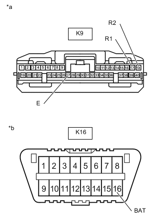
*a Front view of wire harness connector
(to Clearance Warning ECU Assembly)
*b Front view of DLC3 Disconnect the clearance warning ECU assembly connector.
-
Measure the resistance according to the value(s) in the table below.
Terminal No. (Symbol) Wiring Color Terminal Description Condition Specified Condition K9-17 (R1) - K9-18 (R2) L - LG HIGH-level CAN bus wire - LOW-level CAN bus wire Cable disconnected from negative (-) battery terminal 54 to 69 Ω K9-17 (R1) - K9-27 (E) L - W-B HIGH-level CAN bus wire - GND Cable disconnected from negative (-) battery terminal 200 Ω or higher K9-18 (R2) - K9-27 (E) LG - W-B LOW-level CAN bus wire - GND Cable disconnected from negative (-) battery terminal 200 Ω or higher K9-17 (R1) - K16-16 (BAT) L - W HIGH-level CAN bus wire - Battery positive (+) Cable disconnected from negative (-) battery terminal 6 kΩ or higher K9-18 (R2) - K16-16 (BAT) LG - W LOW-level CAN bus wire - Battery positive (+) Cable disconnected from negative (-) battery terminal 6 kΩ or higher
-
-
CHECK DRIVING SUPPORT ECU ASSEMBLY (w/ Pre-crash Safety System)
-
Refer to Terminals of ECU for Dynamic Radar Cruise Control System for further details.
-
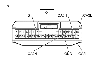
*a Front view of wire harness connector
(to Driving Support ECU Assembly)
Disconnect the driving support ECU assembly connector.
-
Measure the resistance according to the value(s) in the table below.
Bus 4 Terminal No. (Symbol) Wiring Color Terminal Description Condition Specified Condition K4-12 (CA3H) - K4-13 (CA3L) G - SB HIGH-level CAN bus wire - LOW-level CAN bus wire Cable disconnected from negative (-) battery terminal 54 to 69 Ω K4-12 (CA3H) - K4-28 (GND) G - BR HIGH-level CAN bus wire - GND Cable disconnected from negative (-) battery terminal 200 Ω or higher K4-13 (CA3L) - K4-28 (GND) SB - BR LOW-level CAN bus wire - GND Cable disconnected from negative (-) battery terminal 200 Ω or higher K4-12 (CA3H) - K4-7 (B) G - L HIGH-level CAN bus wire - Battery positive (+) Cable disconnected from negative (-) battery terminal 6 kΩ or higher K4-13 (CA3L) - K4-7 (B) SB - L LOW-level CAN bus wire - Battery positive (+) Cable disconnected from negative (-) battery terminal 6 kΩ or higher Bus 5 Terminal No. (Symbol) Wiring Color Terminal Description Condition Specified Condition K4-10 (CA2H) - K4-11 (CA2L) L - LG HIGH-level CAN bus wire - LOW-level CAN bus wire Cable disconnected from negative (-) battery terminal 54 to 69 Ω K4-10 (CA2H) - K4-28 (GND) L - BR HIGH-level CAN bus wire - GND Cable disconnected from negative (-) battery terminal 200 Ω or higher K4-11 (CA2L) - K4-28 (GND) LG - BR LOW-level CAN bus wire - GND Cable disconnected from negative (-) battery terminal 200 Ω or higher K4-10 (CA2H) - K4-7 (B) L - L HIGH-level CAN bus wire - Battery positive (+) Cable disconnected from negative (-) battery terminal 6 kΩ or higher K4-11 (CA2L) - K4-7 (B) LG - L LOW-level CAN bus wire - Battery positive (+) Cable disconnected from negative (-) battery terminal 6 kΩ or higher
-
-
CHECK YAW RATE AND ACCELERATION SENSOR (YAW RATE SENSOR)

-
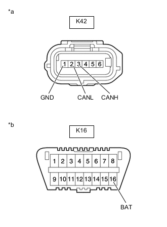
*a Front view of wire harness connector
(to Yaw Rate and Acceleration Sensor (Yaw Rate Sensor))
*b Front view of DLC3 Disconnect the yaw rate and acceleration sensor (yaw rate sensor) connector.
-
Measure the resistance according to the value(s) in the table below.
Terminal No. (Symbol) Wiring Color Terminal Description Condition Specified Condition K42-3 (CANH) - K42-2 (CANL) V - W HIGH-level CAN bus wire - LOW-level CAN bus wire Cable disconnected from negative (-) battery terminal 54 to 69 Ω K42-3 (CANH) - K42-1 (GND) V - W-B HIGH-level CAN bus wire - GND Cable disconnected from negative (-) battery terminal 200 Ω or higher K42-2 (CANL) - K42-1 (GND) W - W-B LOW-level CAN bus wire - GND Cable disconnected from negative (-) battery terminal 200 Ω or higher K42-3 (CANH) - K16-16 (BAT) V - W HIGH-level CAN bus wire - Battery positive (+) Cable disconnected from negative (-) battery terminal 6 kΩ or higher K42-2 (CANL) - K16-16 (BAT) W - W LOW-level CAN bus wire - Battery positive (+) Cable disconnected from negative (-) battery terminal 6 kΩ or higher
-
-
CHECK FORWARD RECOGNITION CAMERA (w/ Pre-crash Safety System)
-
Refer to Terminals of ECU for Pre-crash Safety System for further details.
-
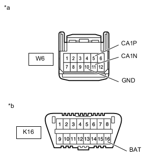
*a Front view of wire harness connector
(to Forward Recognition Camera)
*b Front view of DLC3 Disconnect the forward recognition camera connector.
-
Measure the resistance according to the value(s) in the table below.
Terminal No. (Symbol) Wiring Color Terminal Description Condition Specified Condition W6-5 (CA1P) - W6-11 (CA1N) L - LG HIGH-level CAN bus wire - LOW-level CAN bus wire Cable disconnected from negative (-) battery terminal 54 to 69 Ω W6-5 (CA1P) - W6-10 (GND) L - W-B HIGH-level CAN bus wire - GND Cable disconnected from negative (-) battery terminal 200 Ω or higher W6-11 (CA1N) - W6-10 (GND) LG - W-B LOW-level CAN bus wire - GND Cable disconnected from negative (-) battery terminal 200 Ω or higher W6-5 (CA1P) - K16-16 (BAT) L - W HIGH-level CAN bus wire - Battery positive (+) Cable disconnected from negative (-) battery terminal 6 kΩ or higher W6-11 (CA1N) - K16-16 (BAT) LG - W LOW-level CAN bus wire - Battery positive (+) Cable disconnected from negative (-) battery terminal 6 kΩ or higher
-
-
CHECK BLIND SPOT MONITOR SENSOR RH (w/ Blind Spot Monitor System)
-
Refer to Terminals of ECU for Blind Spot Monitor System for further details.
-
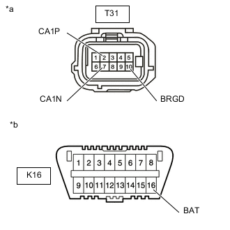
*a Front view of wire harness connector
(to Blind Spot Monitor Sensor RH)
*b Front view of DLC3 Disconnect the blind spot monitor sensor RH connector.
-
Measure the resistance according to the value(s) in the table below.
Terminal No. (Symbol) Wiring Color Terminal Description Condition Specified Condition T31-2 (CA1P) - T31-7 (CA1N) L - LG HIGH-level CAN bus wire - LOW-level CAN bus wire Cable disconnected from negative (-) battery terminal 54 to 69 Ω T31-2 (CA1P) - T31-10 (BRGD) L - W-B HIGH-level CAN bus wire - GND Cable disconnected from negative (-) battery terminal 200 Ω or higher T31-7 (CA1N) - T31-10 (BRGD) LG - W-B LOW-level CAN bus wire - GND Cable disconnected from negative (-) battery terminal 200 Ω or higher T31-2 (CA1P) - K16-16 (BAT) L - W HIGH-level CAN bus wire - Battery positive (+) Cable disconnected from negative (-) battery terminal 6 kΩ or higher T31-7 (CA1N) - K16-16 (BAT) LG - W LOW-level CAN bus wire - Battery positive (+) Cable disconnected from negative (-) battery terminal 6 kΩ or higher
-
-
CHECK FRONT MULTIPLEX NETWORK DOOR ECU LH
-
Refer to Terminals of ECU for Power Mirror Control System for further details.
-
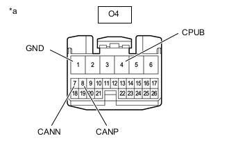
*a Front view of wire harness connector
(to Front Multiplex Network Door ECU LH)
Disconnect the front multiplex network door ECU LH connector.
-
Measure the resistance according to the value(s) in the table below.
Terminal No. (Symbol) Wiring Color Terminal Description Condition Specified Condition O4-8 (CANP) - O4-7 (CANN) R - G HIGH-level CAN bus wire - LOW-level CAN bus wire Cable disconnected from negative (-) battery terminal 54 to 69 Ω O4-8 (CANP) - O4-1 (GND) R - W-B HIGH-level CAN bus wire - GND Cable disconnected from negative (-) battery terminal 200 Ω or higher O4-7 (CANN) - O4-1 (GND) G - W-B LOW-level CAN bus wire - GND Cable disconnected from negative (-) battery terminal 200 Ω or higher O4-8 (CANP) - O4-4 (CPUB) R - P HIGH-level CAN bus wire - Battery positive (+) Cable disconnected from negative (-) battery terminal 6 kΩ or higher O4-7 (CANN) - O4-4 (CPUB) G - P LOW-level CAN bus wire - Battery positive (+) Cable disconnected from negative (-) battery terminal 6 kΩ or higher
-
-
CHECK FRONT MULTIPLEX NETWORK DOOR ECU RH
-
Refer to Terminals of ECU for Power Mirror Control System for further details.
-
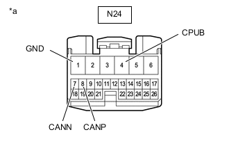
*a Front view of wire harness connector
(to Front Multiplex Network Door ECU RH)
Disconnect the front multiplex network door ECU RH connector.
-
Measure the resistance according to the value(s) in the table below.
Terminal No. (Symbol) Wiring Color Terminal Description Condition Specified Condition N24-8 (CANP) - N24-7 (CANN) R - G HIGH-level CAN bus wire - LOW-level CAN bus wire Cable disconnected from negative (-) battery terminal 54 to 69 Ω N24-8 (CANP) - N24-1 (GND) R - W-B HIGH-level CAN bus wire - GND Cable disconnected from negative (-) battery terminal 200 Ω or higher N24-7 (CANN) - N24-1 (GND) G - W-B LOW-level CAN bus wire - GND Cable disconnected from negative (-) battery terminal 200 Ω or higher N24-8 (CANP) - N24-4 (CPUB) R - P HIGH-level CAN bus wire - Battery positive (+) Cable disconnected from negative (-) battery terminal 6 kΩ or higher N24-7 (CANN) - N24-4 (CPUB) G - P LOW-level CAN bus wire - Battery positive (+) Cable disconnected from negative (-) battery terminal 6 kΩ or higher
-
-
CHECK LUGGAGE CLOSER MOTOR ASSEMBLY (w/ Power Trunk Lid System)
-
Refer to Terminals of ECU for Luggage Compartment Door Opener System for further details.
-
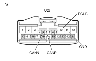
*a Front view of wire harness connector
(to Luggage Closer Motor Assembly)
Disconnect the luggage closer motor assembly connector.
-
Measure the resistance according to the value(s) in the table below.
Terminal No. (Symbol) Wiring Color Terminal Description Condition Specified Condition U28-6 (CANP) - U28-5 (CANN) G - GR HIGH-level CAN bus wire - LOW-level CAN bus wire Cable disconnected from negative (-) battery terminal 54 to 69 Ω U28-6 (CANP) - U28-11 (GND) G - W-B HIGH-level CAN bus wire - GND Cable disconnected from negative (-) battery terminal 200 Ω or higher U28-5 (CANN) - U28-11 (GND) GR - W-B LOW-level CAN bus wire - GND Cable disconnected from negative (-) battery terminal 200 Ω or higher U28-6 (CANP) - U28-10 (ECUB) G - P HIGH-level CAN bus wire - Battery positive (+) Cable disconnected from negative (-) battery terminal 6 kΩ or higher U28-5 (CANN) - U28-10 (ECUB) GR - P LOW-level CAN bus wire - Battery positive (+) Cable disconnected from negative (-) battery terminal 6 kΩ or higher
-
-
CHECK MULTIPLEX NETWORK DOOR ECU (w/o Power Trunk Lid System)
-
Refer to Terminals of ECU for Luggage Compartment Door Closer System for further details.
-
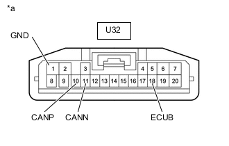
*a Front view of wire harness connector
(to Multiplex Network Door ECU)
Disconnect the multiplex network door ECU connector.
-
Measure the resistance according to the value(s) in the table below.
Terminal No. (Symbol) Wiring Color Terminal Description Condition Specified Condition U32-10 (CANP) - U32-11 (CANN) G - GR HIGH-level CAN bus wire - LOW-level CAN bus wire Cable disconnected from negative (-) battery terminal 54 to 69 Ω U32-10 (CANP) - U32-1 (GND) G - W-B HIGH-level CAN bus wire - GND Cable disconnected from negative (-) battery terminal 200 Ω or higher U32-11 (CANN) - U32-1 (GND) GR - W-B LOW-level CAN bus wire - GND Cable disconnected from negative (-) battery terminal 200 Ω or higher U32-10 (CANP) - U32-18 (ECUB) G - P HIGH-level CAN bus wire - Battery positive (+) Cable disconnected from negative (-) battery terminal 6 kΩ or higher U32-11 (CANN) - U32-18 (ECUB) GR - P LOW-level CAN bus wire - Battery positive (+) Cable disconnected from negative (-) battery terminal 6 kΩ or higher
-
-
CHECK POSITION CONTROL ECU AND SWITCH ASSEMBLY LH
-
Refer to Terminals of ECU for Front Power Seat Control System for further details.
-
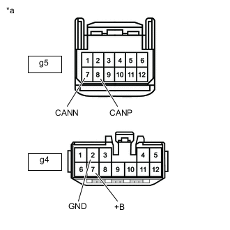
*a Front view of wire harness connector
(to Position Control ECU and Switch Assembly LH)
Disconnect the position control ECU and switch assembly LH connectors.
-
Measure the resistance according to the value(s) in the table below.
Terminal No. (Symbol) Wiring Color Terminal Description Condition Specified Condition g5-8(CANP) - g5-7(CANN) L - W HIGH-level CAN bus wire - LOW-level CAN bus wire Cable disconnected from negative (-) battery terminal 54 to 69 Ω g5-8(CANP) - g4-2(GND) L - W-B HIGH-level CAN bus wire - GND Cable disconnected from negative (-) battery terminal 200 Ω or higher g5-7(CANN) - g4-2(GND) W - W-B LOW-level CAN bus wire - GND Cable disconnected from negative (-) battery terminal 200 Ω or higher g5-8(CANP) - g4-7(+B) L - W HIGH-level CAN bus wire - Battery positive (+) Cable disconnected from negative (-) battery terminal 6 kΩ or higher g5-7(CANN) - g4-7(+B) W - W LOW-level CAN bus wire - Battery positive (+) Cable disconnected from negative (-) battery terminal 6 kΩ or higher
-
-
CHECK POSITION CONTROL ECU AND SWITCH ASSEMBLY RH
-
Refer to Terminals of ECU for Front Power Seat Control System for further details.
-
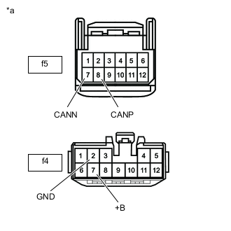
*a Front view of wire harness connector
(to Position Control ECU and Switch Assembly RH)
Disconnect the position control ECU and switch assembly RH connectors.
-
Measure the resistance according to the value(s) in the table below.
Terminal No. (Symbol) Wiring Color Terminal Description Condition Specified Condition f5-8(CANP) - f5-7(CANN) L - W HIGH-level CAN bus wire - LOW-level CAN bus wire Cable disconnected from negative (-) battery terminal 54 to 69 Ω f5-8(CANP) - f4-2(GND) L - W-B HIGH-level CAN bus wire - GND Cable disconnected from negative (-) battery terminal 200 Ω or higher f5-7(CANN) - f4-2(GND) W - W-B LOW-level CAN bus wire - GND Cable disconnected from negative (-) battery terminal 200 Ω or higher f5-8(CANP) - f4-7(+B) L - W HIGH-level CAN bus wire - Battery positive (+) Cable disconnected from negative (-) battery terminal 6 kΩ or higher f5-7(CANN) - f4-7(+B) W - W LOW-level CAN bus wire - Battery positive (+) Cable disconnected from negative (-) battery terminal 6 kΩ or higher
-
-
CHECK MULTIPLEX TILT AND TELESCOPIC ECU
-
Refer to Terminals of ECU for Power Tilt and Power Telescopic Steering Column System for further details.
-
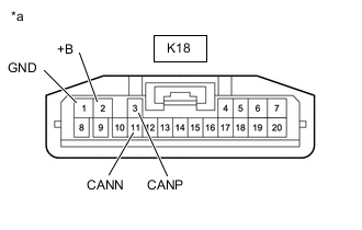
*a Front view of wire harness connector
(to Multiplex Tilt and Telescopic ECU)
Disconnect the multiplex tilt and telescopic ECU connector.
-
Measure the resistance according to the value(s) in the table below.
Terminal No. (Symbol) Wiring Color Terminal Description Condition Specified Condition K18-3 (CANP) - K18-11 (CANN) R - GR HIGH-level CAN bus wire - LOW-level CAN bus wire Cable disconnected from negative (-) battery terminal 54 to 69 Ω K18-3 (CANP) - K18-1 (GND) R - W-B HIGH-level CAN bus wire - GND Cable disconnected from negative (-) battery terminal 200 Ω or higher K18-11 (CANN) - K18-1 (GND) GR - W-B LOW-level CAN bus wire - GND Cable disconnected from negative (-) battery terminal 200 Ω or higher K18-3 (CANP) - K18-2 (+B) R - L HIGH-level CAN bus wire - Battery positive (+) Cable disconnected from negative (-) battery terminal 6 kΩ or higher K18-11 (CANN) - K18-2 (+B) GR - L LOW-level CAN bus wire - Battery positive (+) Cable disconnected from negative (-) battery terminal 6 kΩ or higher
-
-
CHECK HEADLIGHT LIGHT CONTROL ECU SUB-ASSEMBLY LH
-
Refer to Terminals of ECU for Lighting System for further details.
-
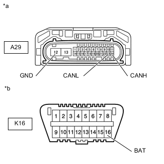
*a Front view of wire harness connector
(to Headlight Light Control ECU Sub-assembly LH)
*b Front view of DLC3 Disconnect the headlight light control ECU sub-assembly LH connector.
-
Measure the resistance according to the value(s) in the table below.
Terminal No. (Symbol) Wiring Color Terminal Description Condition Specified Condition A29-24 (CANH) - A29-23 (CANL) P - W HIGH-level CAN bus wire - LOW-level CAN bus wire Cable disconnected from negative (-) battery terminal 54 to 69 Ω A29-24 (CANH) - A29-12 (GND) P - W-B HIGH-level CAN bus wire - GND Cable disconnected from negative (-) battery terminal 200 Ω or higher A29-23 (CANL) - A29-12 (GND) W - W-B LOW-level CAN bus wire - GND Cable disconnected from negative (-) battery terminal 200 Ω or higher A29-24 (CANH) - K16-16 (BAT) P - W HIGH-level CAN bus wire - Battery positive (+) Cable disconnected from negative (-) battery terminal 6 kΩ or higher A29-23 (CANL) - K16-16 (BAT) W - W LOW-level CAN bus wire - Battery positive (+) Cable disconnected from negative (-) battery terminal 6 kΩ or higher
-
-
CHECK MILLIMETER WAVE RADAR SENSOR ASSEMBLY (w/ Pre-crash Safety System)
-
Refer to Terminals of ECU for Dynamic Radar Cruise Control System for further details.
-
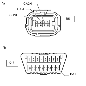
*a Front view of wire harness connector
(to Millimeter Wave Radar Sensor Assembly)
*b Front view of DLC3 Disconnect the millimeter wave radar sensor assembly connector.
-
Measure the resistance according to the value(s) in the table below.
Terminal No. (Symbol) Wiring Color Terminal Description Condition Specified Condition B5-3 (CA2H) - B5-2 (CA2L) B - L HIGH-level CAN bus wire - LOW-level CAN bus wire Cable disconnected from negative (-) battery terminal 54 to 69 Ω B5-3 (CA2H) - B5-1 (SGND) B - BR HIGH-level CAN bus wire - GND Cable disconnected from negative (-) battery terminal 200 Ω or higher B5-2 (CA2L) - B5-1 (SGND) L - BR LOW-level CAN bus wire - GND Cable disconnected from negative (-) battery terminal 200 Ω or higher B5-3 (CA2H) - K16-16 (BAT) B - W HIGH-level CAN bus wire - Battery positive (+) Cable disconnected from negative (-) battery terminal 6 kΩ or higher B5-2 (CA2L) - K16-16 (BAT) L - W LOW-level CAN bus wire - Battery positive (+) Cable disconnected from negative (-) battery terminal 6 kΩ or higher
-
-
CHECK ABSORBER CONTROL ECU
-
Refer to Terminals of ECU for Adaptive Variable Suspension System for further details.
-
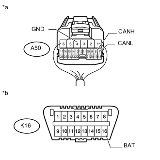
*a Rear view of wire harness connector
(to Absorber Control ECU)
*b Front view of DLC3 Disconnect the absorber control ECU connector.
-
Measure the resistance according to the value(s) in the table below.
Terminal No. (Symbol) Wiring Color Terminal Description Condition Specified Condition A50-8 (CANH) - A50-7 (CANL) V - LG HIGH-level CAN bus line - LOW-level CAN bus line Cable disconnected from negative (-) battery terminal 54 to 69 Ω A50-8 (CANH) - A50-4 (GND) V - W-B HIGH-level CAN bus line - Ground Cable disconnected from negative (-) battery terminal 200 Ω or higher A50-7 (CANL) - A50-4 (GND) LG - W-B LOW-level CAN bus line - Ground Cable disconnected from negative (-) battery terminal 200 Ω or higher A50-8 (CANH) - K16-16 (BAT) V - W HIGH-level CAN bus line - Battery positive (+) Cable disconnected from negative (-) battery terminal 6 kΩ or higher A50-7 (CANL) - K16-16 (BAT) LG - W LOW-level CAN bus line - Battery positive (+) Cable disconnected from negative (-) battery terminal 6 kΩ or higher
-
-
CHECK TELEMATICS TRANSCEIVER (w/ Telematics Transceiver)
-
Refer to Terminals of ECU for Telematics Transceiver for further details.
-
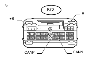
*a Front view of wire harness connector
(to Telematics Transceiver)
Disconnect the telematics transceiver connector.
-
Measure the resistance according to the value(s) in the table below.
Terminal No. (Symbol) Wiring Color Terminal Description Condition Specified Condition K70-15 (CANP) - K70-16 (CANN) B - W HIGH-level CAN bus line - LOW-level CAN bus line Cable disconnected from negative (-) battery terminal 54 to 69 Ω K70-15 (CANP) - K70-4 (E) B - W-B HIGH-level CAN bus line - Ground Cable disconnected from negative (-) battery terminal 200 Ω or higher K70-16 (CANN) - K70-4 (E) W - W-B LOW-level CAN bus line - Ground Cable disconnected from negative (-) battery terminal 200 Ω or higher K70-15 (CANP) - K70-1 (+B) B - B HIGH-level CAN bus line - Battery positive (+) Cable disconnected from negative (-) battery terminal 6 kΩ or higher K70-16 (CANN) - K70-1 (+B) W - B LOW-level CAN bus line - Battery positive (+) Cable disconnected from negative (-) battery terminal 6 kΩ or higher
-