CLEARANCE WARNING ECU INSTALLATION
PROCEDURE
-
INSTALL CLEARANCE WARNING ECU ASSEMBLY (for LHD)
-
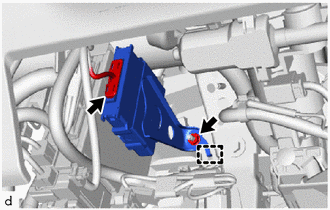
Engage the hook to install the clearance warning ECU assembly with the nut.
Note
Replace the clearance warning ECU assembly if it has been dropped or subjected to a severe impact.
-
Connect the connector.
-
-
INSTALL CLEARANCE WARNING ECU ASSEMBLY (for RHD)
-
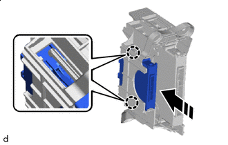

Install in this Direction Engage the claws to install the clearance warning ECU assembly as shown in the illustration.
Note
Replace the clearance warning ECU assembly if it has been dropped or subjected to a severe impact.
-
-
INSTALL COWL SIDE JUNCTION BLOCK LH (for RHD)
-
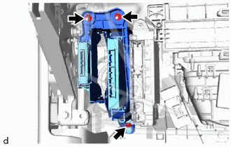
Install the cowl side junction block LH with the 2 nuts and bolt.
- Torque:
- Nut
- 8.5 N*m { 87 kgf*cm, 75 in.*lbf }
- Bolt
- 8.5 N*m { 87 kgf*cm, 75 in.*lbf }
-
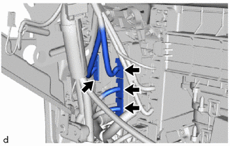
Connect the 4 connectors.
-
-
INSTALL LOWER NO. 1 INSTRUMENT PANEL AIRBAG ASSEMBLY (for LHD)
-
INSTALL GLOVE COMPARTMENT DOOR ASSEMBLY (for RHD)
-
CONNECT CABLE TO NEGATIVE BATTERY TERMINAL
Note
When disconnecting the cable, some systems need to be initialized after the cable is reconnected.
-
PERFORM DIAGNOSTIC SYSTEM CHECK
-
INSPECT SRS WARNING LIGHT