LEXUS PARKING ASSIST-SENSOR SYSTEM Clearance Sonar Main Switch Circuit
DESCRIPTION
The back sonar or clearance sonar switch assembly is installed at the base of the lower instrument panel finish panel sub-assembly.
When the back sonar or clearance sonar switch assembly is turned on, an on signal is sent to the clearance warning ECU assembly. The LEXUS parking assist-sensor system operates according to this signal.
WIRING DIAGRAM
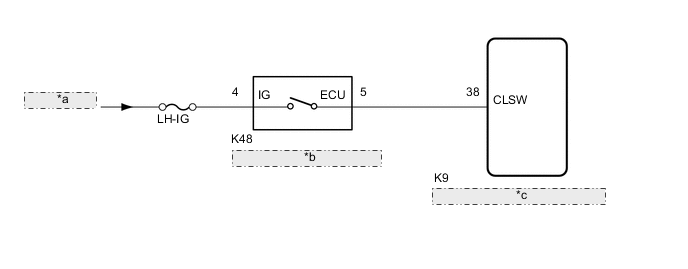
| *a | from LH-IG1 RLY1 Relay |
| *b | Back Sonar or Clearance Sonar Switch Assembly |
| *c | Clearance Warning ECU Assembly |
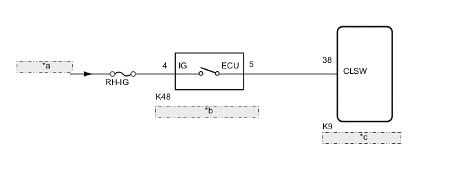
| *a | from RH-IG1 RLY1 Relay |
| *b | Back Sonar or Clearance Sonar Switch Assembly |
| *c | Clearance Warning ECU Assembly |
CAUTION / NOTICE / HINT
Note
Inspect the fuses for circuits related to this system before performing the following procedure.
PROCEDURE
-
READ VALUE USING GTS
-
Connect the GTS to the DLC3.
-
Turn the engine switch on (IG).
-
Turn the GTS on.
-
Enter the following menus: Body Electrical / Clearance Sonar / Data List.
-
According to the display on the GTS, read the Data List.
Body Electrical > Clearance Sonar > Data ListTester Display Measurement Item Range Normal Condition Diagnostic Note Clearance Sonar ECU Clearance warning ECU assembly information Normal or Abnormal Normal: Clearance warning ECU assembly normal
Abnormal: Clearance warning ECU assembly not normal
-
Body Electrical > Clearance Sonar > Data ListTester Display Clearance Sonar ECU Result Result Proceed to "Normal" is displayed. A "Abnormal" is displayed. B
B 
REPLACE CLEARANCE WARNING ECU ASSEMBLY Click here
A 
-
-
READ VALUE USING GTS
-
Connect the GTS to the DLC3.
-
Turn the engine switch on (IG).
-
Turn the GTS on.
-
Enter the following menus: Body Electrical / Clearance Sonar / Data List.
-
According to the display on the GTS, read the Data List.
Body Electrical > Clearance Sonar > Data ListTester Display Measurement Item Range Normal Condition Diagnostic Note Main Switch Back sonar or clearance sonar switch assembly OFF or ON OFF: Back sonar or clearance sonar switch assembly off
ON: Back sonar or clearance sonar switch assembly on
-
Body Electrical > Clearance Sonar > Data ListTester Display Main Switch Result Result Proceed to The display does not change as shown above when the back sonar or clearance sonar switch assembly is operated. A The display changes as shown above when the back sonar or clearance sonar switch assembly is operated. B
B
REPLACE CLEARANCE WARNING ECU ASSEMBLY Click here
A
-
-
INSPECT BACK SONAR OR CLEARANCE SONAR SWITCH ASSEMBLY
-
Remove the back sonar or clearance sonar switch assembly.
-
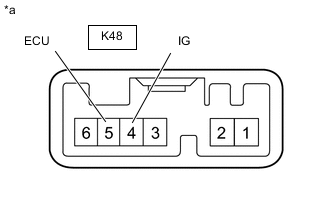
*a Component without harness connected
(Back Sonar Clearance Sonar Switch Assembly)
Measure the resistance according to the value(s) in the table below.
Standard Resistance Tester Connection Condition Specified Condition K48-4 (IG) - K48-5 (ECU) Back sonar or clearance sonar switch assembly pushed Below 1Ω K48-4 (IG) - K48-5 (ECU) Back sonar or clearance sonar switch assembly not pushed 10 kΩ or higher Result Proceed to OK NG
NG
REPLACE BACK SONAR OR CLEARANCE SONAR SWITCH ASSEMBLY Click here
OK
-
-
CHECK HARNESS AND CONNECTOR (BACK SONAR OR CLEARANCE SONAR SWITCH ASSEMBLY - BATTERY)
-
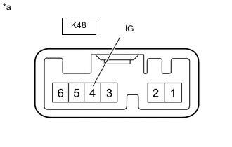
*a Component without harness connected
(Back Sonar Clearance Sonar Switch Assembly)
Measure the voltage according to the value(s) in the table below.
Standard Voltage Tester Connection Condition Specified Condition K48-4 (IG) - Body ground Engine switch on (IG) 11 to 14 V K48-4 (IG) - Body ground Engine switch off Below 1 V Result Proceed to OK NG
NG
REPAIR OR REPLACE HARNESS OR CONNECTOR
OK
-
-
CHECK HARNESS AND CONNECTOR (CLEARANCE WARNING ECU ASSEMBLY - BACK SONAR OR CLEARANCE SONAR SWITCH ASSEMBLY)
-
Measure the resistance according to the value(s) in the table below.
Standard Resistance Tester Connection Condition Specified Condition K9-38 (CLSW) - K48-5 (ECU) Always Below 1 Ω K9-38 (CLSW) - Body ground Always 10 kΩ or higher Result Proceed to OK NG
OK
REPLACE CLEARANCE WARNING ECU ASSEMBLY Click here
NG
REPAIR OR REPLACE HARNESS OR CONNECTOR
-