NAVIGATION SYSTEM Visual Mute Signal Circuit between Navigation Receiver Assembly and Multi-display
DESCRIPTION
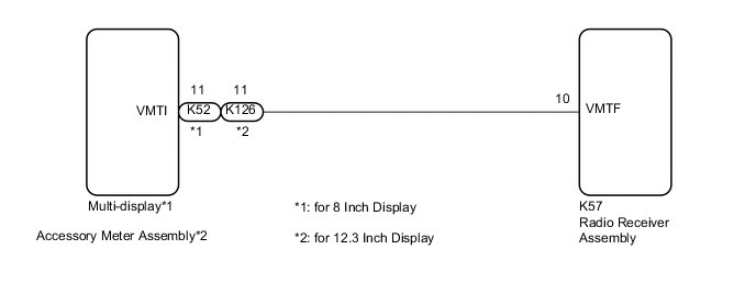
The radio receiver assembly sends a visual mute signal to the multi-display*1 or accessory meter assembly*2.
As a result, a black screen is displayed when the screen changes so that noise and distorted images are not displayed.
When an open exists in the circuit, noise and distorted images will be displayed instead of a black screen.
When a short exists in the circuit, even though the multi-display*1 or accessory meter assembly*2 is operating normally, noise and distorted images will be displayed (black screen will not be displayed) during screen changes or the black screen will always be displayed.
-
*1: for 8 Inch Display
-
*2: for 12.3 Inch Display
WIRING DIAGRAM
CAUTION / NOTICE / HINT
Note
Depending on the parts that are replaced during vehicle inspection or maintenance, performing initialization, registration or calibration may be needed.
PROCEDURE
-
CHECK MODEL
-
Choose the model to be inspected.
Result Result Proceed to for 8 Inch Display A for 12.3 Inch Display B
B 
INSPECT ACCESSORY METER ASSEMBLY Click here
A 
-
-
INSPECT MULTI-DISPLAY
-
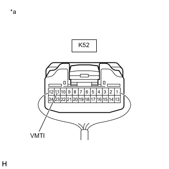
*a Component with harness connected
(Multi-display)
Measure the voltage according to the value(s) in the table below.
Standard Voltage Tester Connection Switch Condition Specified Condition K52-11 (VMTI) - Body ground Engine switch on (ACC), screen display changes 3.5 V or higher
→ Below 1 V
→ 3.5 V or higher
Result Proceed to OK NG
OK 
PROCEED TO NEXT SUSPECTED AREA SHOWN IN PROBLEM SYMPTOMS TABLE Click here
NG
-
-
CHECK HARNESS AND CONNECTOR (RADIO RECEIVER ASSEMBLY - MULTI-DISPLAY)
-
Disconnect the K57 radio receiver assembly.
-
Disconnect the K52 multi-display connector.
-
Measure the resistance according to the value(s) in the table below.
Standard Resistance Tester Connection Condition Specified Condition K57-10 (VMTF) - K52-11 (VMTI) Always Below 1 Ω K57-10 (VMTF) or K52-11 (VMTI) - Body ground Always 10 kΩ or higher Result Proceed to OK NG
NG
REPAIR OR REPLACE HARNESS OR CONNECTOR
OK
-
-
REPLACE MULTI-DISPLAY
-
Replace the multi-display with a new or known good one.
-
Check that the screen display is normal.
OK Screen display is normal. Result Proceed to OK NG
OK
END
NG
REPLACE RADIO RECEIVER ASSEMBLY Click here
-
-
INSPECT ACCESSORY METER ASSEMBLY
-
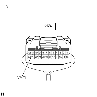
*a Component with harness connected
(Accessory Meter Assembly)
Measure the voltage according to the value(s) in the table below.
Standard Voltage Tester Connection Switch Condition Specified Condition K126-11 (VMTI) - Body ground Engine switch on (ACC), screen display changes 3.5 V or higher
→ Below 1 V
→ 3.5 V or higher
Result Proceed to OK NG
OK
PROCEED TO NEXT SUSPECTED AREA SHOWN IN PROBLEM SYMPTOMS TABLE Click here
NG
-
-
CHECK HARNESS AND CONNECTOR (RADIO RECEIVER ASSEMBLY - ACCESSORY METER ASSEMBLY)
-
Disconnect the K57 radio receiver assembly.
-
Disconnect the K126 accessory meter assembly connector.
-
Measure the resistance according to the value(s) in the table below.
Standard Resistance Tester Connection Condition Specified Condition K57-10 (VMTF) - K126-11 (VMTI) Always Below 1 Ω K57-10 (VMTF) or K126-11 (VMTI) - Body ground Always 10 kΩ or higher Result Proceed to OK NG
NG
REPAIR OR REPLACE HARNESS OR CONNECTOR
OK
-
-
REPLACE ACCESSORY METER ASSEMBLY
-
Replace the accessory meter assembly with a new or known good one.
-
Check that the screen display is normal.
OK Screen display is normal. Result Proceed to OK NG
OK
END
NG
REPLACE RADIO RECEIVER ASSEMBLY Click here
-