NAVIGATION SYSTEM Speaker Circuit
DESCRIPTION
If there is a short in a speaker circuit, the stereo component amplifier assembly detects it and stops output to the speakers.
Thus sound cannot be heard from the speakers even if there is no malfunction in the stereo component amplifier assembly or speakers.
WIRING DIAGRAM
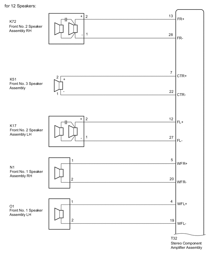
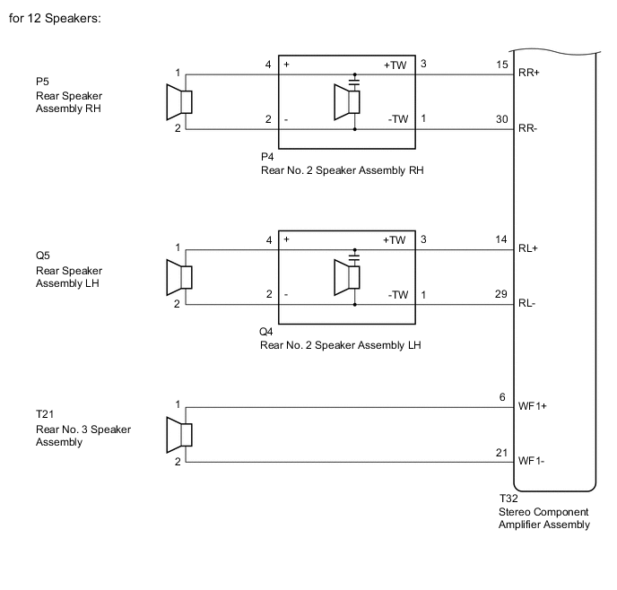
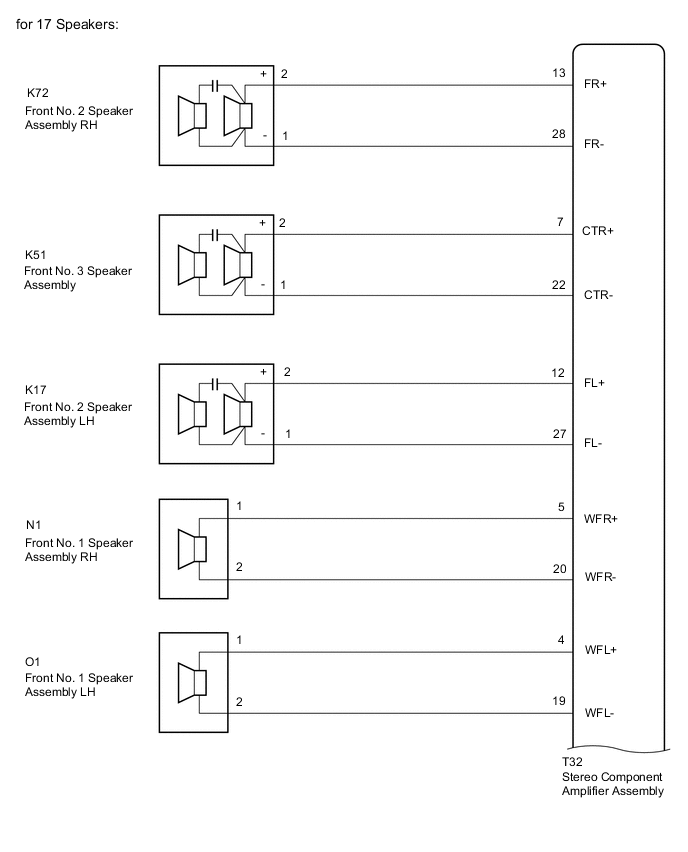
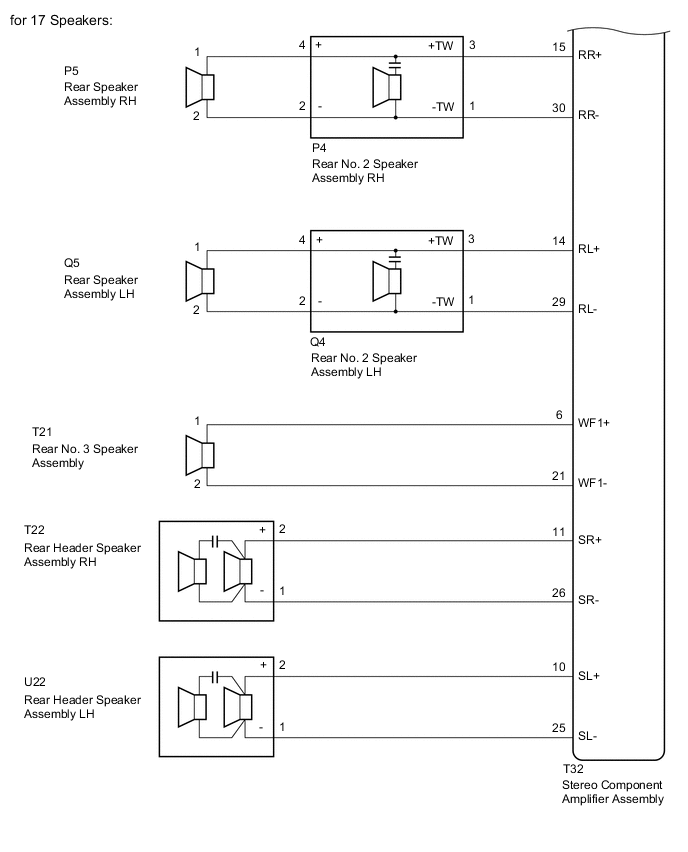
CAUTION / NOTICE / HINT
Note
Depending on the parts that are replaced during vehicle inspection or maintenance, performing initialization, registration or calibration may be needed.
PROCEDURE
-
CHECK MODEL
-
Choose the model to be inspected.
Result Result Proceed to for 12 Speakers A for 17 Speakers B
B 
CHECK SPEAKER (OPERATION CHECK) Click here
A 
-
-
CHECK SPEAKER (OPERATION CHECK)
-
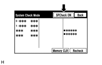
Enter the "System Check Mode" screen. Refer to Check SP Check On in Operation Check.
-
Perform the operation check above and determine the speaker that is not operating.
Result Not Operating Speaker Proceed to Front No. 1 speaker assembly A Front No. 2 speaker assembly B Front No. 3 speaker assembly C Rear speaker assembly or rear No. 2 speaker assembly D Rear No. 3 speaker assembly E Tech Tips
If sound cannot be heard from any speaker, inspect all of them.
B
CHECK HARNESS AND CONNECTOR (STEREO COMPONENT AMPLIFIER ASSEMBLY - FRONT NO. 2 SPEAKER ASSEMBLY) Click here
C
CHECK HARNESS AND CONNECTOR (STEREO COMPONENT AMPLIFIER ASSEMBLY - FRONT NO. 3 SPEAKER ASSEMBLY) Click here
D
CHECK HARNESS AND CONNECTOR (STEREO COMPONENT AMPLIFIER ASSEMBLY - REAR NO. 2 SPEAKER ASSEMBLY) Click here
E
CHECK HARNESS AND CONNECTOR (STEREO COMPONENT AMPLIFIER ASSEMBLY - REAR NO. 3 SPEAKER ASSEMBLY) Click here
A
-
-
CHECK HARNESS AND CONNECTOR (STEREO COMPONENT AMPLIFIER ASSEMBLY - FRONT NO. 1 SPEAKER ASSEMBLY)
-
Disconnect the T32 stereo component amplifier assembly connector.
-
Disconnect the K72 and K17 front No. 1 speaker assembly connectors.
-
Measure the resistance between the stereo component amplifier assembly and the front No. 1 speaker assemblies to check for an open in the wire harness.
Standard Resistance Tester Connection Condition Specified Condition T32-13 (FR+) - K72-2 (+) Always Below 1 Ω T32-28 (FR-) - K72-1 (-) Always Below 1 Ω T32-12 (FL+) - K17-2 (+) Always Below 1 Ω T32-27 (FL-) - K17-1 (-) Always Below 1 Ω -
Measure the resistance between the stereo component amplifier assembly or the front No. 1 speaker assemblies and body ground to check for a short in the wire harness.
Standard Resistance Tester Connection Condition Specified Condition T32-13 (FR+) or K72-2 (+) - Body ground Always 10 kΩ or higher T32-28 (FR-) or K72-1 (-) - Body ground Always 10 kΩ or higher T32-12 (FL+) or K17-2 (+) - Body ground Always 10 kΩ or higher T32-27 (FL-) or K17-1 (-) - Body ground Always 10 kΩ or higher Result Proceed to OK NG
NG 
REPAIR OR REPLACE HARNESS OR CONNECTOR
OK
-
-
INSPECT FRONT NO. 1 SPEAKER ASSEMBLY
-
Remove the front No. 1 speaker assembly.
-
Inspect the front No. 1 speaker assembly.
Result proceed to OK NG
OK
PROCEED TO NEXT SUSPECTED AREA SHOWN IN PROBLEM SYMPTOMS TABLE Click here
NG
REPLACE FRONT NO. 1 SPEAKER ASSEMBLY Click here
-
-
CHECK HARNESS AND CONNECTOR (STEREO COMPONENT AMPLIFIER ASSEMBLY - FRONT NO. 2 SPEAKER ASSEMBLY)
-
Disconnect the T32 stereo component amplifier assembly connector.
-
Disconnect the N1 and O1 front No. 2 speaker assembly connectors.
-
Measure the resistance between the stereo component amplifier assembly and each of the front No. 2 speaker assemblies to check for an open in the wire harness.
Standard Resistance Tester Connection Condition Specified Condition T32-5 (WFR+) - N1-1 Always Below 1 Ω T32-20 (WFR-) - N1-2 Always Below 1 Ω T32-4 (WFL+) - O1-1 Always Below 1 Ω T32-19 (WFL-) - O1-2 Always Below 1 Ω -
Measure the resistance between the stereo component amplifier assembly or each of the front No. 2 speaker assemblies and body ground to check for a short in the wire harness.
Standard Resistance Tester Connection Condition Specified Condition T32-5 (WFR+) or N1-1 - Body ground Always 10 kΩ or higher T32-20 (WFR-) or N1-2 - Body ground Always 10 kΩ or higher T32-4 (WFL+) or O1-1 - Body ground Always 10 kΩ or higher T32-19 (WFL-) or O1-2 - Body ground Always 10 kΩ or higher Result Proceed to OK NG
NG
REPAIR OR REPLACE HARNESS OR CONNECTOR
OK
-
-
INSPECT FRONT NO. 2 SPEAKER ASSEMBLY
-
Remove the front No. 2 speaker assembly.
-
Check that the malfunction disappears when a new or known good front No. 2 speaker assembly is installed.
OK Malfunction disappears. Result Proceed to OK NG
OK
END
NG
PROCEED TO NEXT SUSPECTED AREA SHOWN IN PROBLEM SYMPTOMS TABLE Click here
-
-
CHECK HARNESS AND CONNECTOR (STEREO COMPONENT AMPLIFIER ASSEMBLY - FRONT NO. 3 SPEAKER ASSEMBLY)
-
Disconnect the T32 stereo component amplifier assembly connector.
-
Disconnect the K51 front No. 3 speaker assembly connector.
-
Measure the resistance between the stereo component amplifier assembly and each of the front No. 3 speaker assembly to check for an open in the wire harness.
Standard Resistance Tester Connection Condition Specified Condition T32-7 (CTR+) - K51-2 (+) Always Below 1 Ω T32-22 (CTR-) - K51-1 (-) Always Below 1 Ω -
Measure the resistance between the stereo component amplifier assembly or each of the front No. 3 speaker assembly and body ground to check for a short in the wire harness.
Standard Resistance Tester Connection Condition Specified Condition T32-7 (CTR+) or K51-2 (+) - Body ground Always 10 kΩ or higher T32-22 (CTR-) or K51-1 (-) - Body ground Always 10 kΩ or higher Result Proceed to OK NG
NG
REPAIR OR REPLACE HARNESS OR CONNECTOR
OK
-
-
INSPECT FRONT NO. 3 SPEAKER ASSEMBLY
-
Remove the front No. 3 speaker assembly.
-
Inspect the front No. 3 speaker assembly.
Result Proceed to OK NG
OK
PROCEED TO NEXT SUSPECTED AREA SHOWN IN PROBLEM SYMPTOMS TABLE Click here
NG
REPLACE FRONT NO. 3 SPEAKER ASSEMBLY Click here
-
-
CHECK HARNESS AND CONNECTOR (STEREO COMPONENT AMPLIFIER ASSEMBLY - REAR NO. 2 SPEAKER ASSEMBLY)
-
Disconnect the T32 stereo component amplifier assembly connector.
-
Disconnect the P4 and Q4 rear No. 2 speaker assembly connectors.
-
Measure the resistance between the stereo component amplifier assembly and each of the rear No. 2 speaker assemblies to check for an open in the wire harness.
Standard Resistance Tester Connection Condition Specified Condition T32-15 (RR+) - P4-3 (+TW) Always Below 1 Ω T32-30 (RR-) - P4-1 (-TW) Always Below 1 Ω T32-14 (RL+) - Q4-3 (+TW) Always Below 1 Ω T32-29 (RL-) - Q4-1 (-TW) Always Below 1 Ω -
Measure the resistance between the stereo component amplifier assembly or each of the rear No. 2 speaker assemblies and body ground to check for a short in the wire harness.
Standard Resistance Tester Connection Condition Specified Condition T32-15 (RR+) or P4-3 (+TW) - Body ground Always 10 kΩ or higher T32-30 (RR-) or P4-1 (-TW) - Body ground Always 10 kΩ or higher T32-14 (RL+) or Q4-3 (+TW) - Body ground Always 10 kΩ or higher T32-29 (RL-) or Q4-1 (-TW) - Body ground Always 10 kΩ or higher Result Proceed to OK NG
NG
REPAIR OR REPLACE HARNESS OR CONNECTOR
OK
-
-
CHECK HARNESS AND CONNECTOR (REAR SPEAKER ASSEMBLY - REAR NO. 2 SPEAKER ASSEMBLY)
-
Disconnect the P5 and Q5 rear speaker assembly connectors.
-
Disconnect the P4 and Q4 rear No. 2 speaker assembly connectors.
-
Measure the resistance between each of the rear speaker assemblies and rear No. 2 speaker assemblies to check for an open in the wire harness.
Standard Resistance Tester Connection Condition Specified Condition P5-1 - P4-4 (+) Always Below 1 Ω P5-2 - P4-2 (-) Always Below 1 Ω Q5-1 - Q4-4 (+) Always Below 1 Ω Q5-2 - Q4-2 (-) Always Below 1 Ω -
Measure the resistance between each of the rear speaker assemblies or rear No. 2 speaker assemblies and body ground to check for a short in the wire harness.
Standard Resistance Tester Connection Condition Specified Condition P5-1 or P4-4 (+) - Body ground Always 10 kΩ or higher P5-2 or P4-2 (-) - Body ground Always 10 kΩ or higher Q5-1 or Q4-4 (+) - Body ground Always 10 kΩ or higher Q5-2 or Q4-2 (-) - Body ground Always 10 kΩ or higher Result Proceed to OK NG
NG
REPAIR OR REPLACE HARNESS OR CONNECTOR
OK
-
-
INSPECT REAR SPEAKER ASSEMBLY
-
Remove the rear speaker assembly.
-
Inspect the rear speaker assembly.
Result Proceed to OK NG
NG
REPLACE REAR SPEAKER ASSEMBLY Click here
OK
-
-
INSPECT REAR NO. 2 SPEAKER ASSEMBLY
-
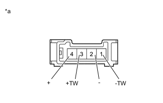
*a Component without harness connected
(Rear No. 2 Speaker Assembly)
Remove the rear No. 2 speaker assembly.
-
Measure the resistance according to the value(s) in the table below.
Standard Resistance Tester Connection Condition Specified Condition 4 (+) - 3 (+TW) Always Below 1 Ω 2 (-) - 1 (-TW) Always Below 1 Ω 4 (+) - 2 (-) Always 10 kΩ or higher Result proceed to OK NG
NG
REPLACE REAR NO. 2 SPEAKER ASSEMBLY Click here
OK
-
-
INSPECT REAR NO. 2 SPEAKER ASSEMBLY
-
Remove the rear No. 2 speaker assembly.
-
Check that the malfunction disappears when a new or known good rear No. 2 speaker assembly is installed.
OK Malfunction disappears. Result Proceed to OK NG
OK
END
NG
PROCEED TO NEXT SUSPECTED AREA SHOWN IN PROBLEM SYMPTOMS TABLE Click here
-
-
CHECK HARNESS AND CONNECTOR (STEREO COMPONENT AMPLIFIER ASSEMBLY - REAR NO. 3 SPEAKER ASSEMBLY)
-
Disconnect the T32 stereo component amplifier assembly connector.
-
Disconnect the T21 rear No. 3 speaker assembly connector.
-
Measure the resistance between the stereo component amplifier assembly and the rear No. 3 speaker assembly to check for an open in the wire harness.
Standard Resistance Tester Connection Condition Specified Condition T32-6 (WF1+) - T21-1 Always Below 1 Ω T32-21 (WF1-) - T21-2 Always Below 1 Ω -
Measure the resistance between the stereo component amplifier assembly or the rear No. 3 speaker assembly and body ground to check for a short in the wire harness.
Standard Resistance Tester Connection Condition Specified Condition T32-6 (WF1+) or T21-1 - Body ground Always 10 kΩ or higher T32-21 (WF1-) or T21-2 - Body ground Always 10 kΩ or higher Result Proceed to OK NG
NG
REPAIR OR REPLACE HARNESS OR CONNECTOR
OK
-
-
INSPECT REAR NO. 3 SPEAKER ASSEMBLY
-
Remove the rear No. 3 speaker assembly.
-
Inspect the rear No. 3 speaker assembly.
Result Proceed to OK NG
OK
PROCEED TO NEXT SUSPECTED AREA SHOWN IN PROBLEM SYMPTOMS TABLE Click here
NG
REPLACE REAR NO.3 SPEAKER ASSEMBLY Click here
-
-
CHECK SPEAKER (OPERATION CHECK)
-
Enter the "System Check Mode" screen. Refer to Check SP Check On in Operation Check.
-
Perform the operation check above and determine the speaker that is not operating.
Result Not Operating Speaker Proceed to Front No. 1 speaker assembly A Front No. 2 speaker assembly B Front No. 3 speaker assembly C Rear speaker assembly or rear No. 2 speaker assembly D Rear No. 3 speaker assembly E Rear header speaker assembly F Tech Tips
If sound cannot be heard from any speaker, inspect all of them.
B
CHECK HARNESS AND CONNECTOR (STEREO COMPONENT AMPLIFIER ASSEMBLY - FRONT NO. 2 SPEAKER ASSEMBLY) Click here
C
CHECK HARNESS AND CONNECTOR (STEREO COMPONENT AMPLIFIER ASSEMBLY - FRONT NO. 3 SPEAKER ASSEMBLY) Click here
D
CHECK HARNESS AND CONNECTOR (STEREO COMPONENT AMPLIFIER ASSEMBLY - REAR NO. 2 SPEAKER ASSEMBLY) Click here
E
CHECK HARNESS AND CONNECTOR (STEREO COMPONENT AMPLIFIER ASSEMBLY - REAR NO. 3 SPEAKER ASSEMBLY) Click here
F
CHECK HARNESS AND CONNECTOR (STEREO COMPONENT AMPLIFIER ASSEMBLY - REAR HEADER SPEAKER ASSEMBLY) Click here
A
-
-
CHECK HARNESS AND CONNECTOR (STEREO COMPONENT AMPLIFIER ASSEMBLY - FRONT NO. 1 SPEAKER ASSEMBLY)
-
Disconnect the T32 stereo component amplifier assembly connector.
-
Disconnect the K72 and K17 front No. 1 speaker assembly connectors.
-
Measure the resistance between the stereo component amplifier assembly and the front No. 1 speaker assemblies to check for an open in the wire harness.
Standard Resistance Tester Connection Condition Specified Condition T32-13 (FR+) - K72-2 (+) Always Below 1 Ω T32-28 (FR-) - K72-1 (-) Always Below 1 Ω T32-12 (FL+) - K17-2 (+) Always Below 1 Ω T32-27 (FL-) - K17-1 (-) Always Below 1 Ω -
Measure the resistance between the stereo component amplifier assembly or the front No. 1 speaker assemblies and body ground to check for a short in the wire harness.
Standard Resistance Tester Connection Condition Specified Condition T32-13 (FR+) or K72-2 (+) - Body ground Always 10 kΩ or higher T32-28 (FR-) or K72-1 (-) - Body ground Always 10 kΩ or higher T32-12 (FL+) or K17-2 (+) - Body ground Always 10 kΩ or higher T32-27 (FL-) or K17-1 (-) - Body ground Always 10 kΩ or higher Result Proceed to OK NG
NG
REPAIR OR REPLACE HARNESS OR CONNECTOR
OK
-
-
INSPECT FRONT NO. 1 SPEAKER ASSEMBLY
-
Remove the front No. 1 speaker assembly.
-
Inspect the front No. 1 speaker assembly.
Result proceed to OK NG
OK
PROCEED TO NEXT SUSPECTED AREA SHOWN IN PROBLEM SYMPTOMS TABLE Click here
NG
REPLACE FRONT NO. 1 SPEAKER ASSEMBLY Click here
-
-
CHECK HARNESS AND CONNECTOR (STEREO COMPONENT AMPLIFIER ASSEMBLY - FRONT NO. 2 SPEAKER ASSEMBLY)
-
Disconnect the T32 stereo component amplifier assembly connector.
-
Disconnect the N1 and O1 front No. 2 speaker assembly connectors.
-
Measure the resistance between the stereo component amplifier assembly and each of the front No. 2 speaker assemblies to check for an open in the wire harness.
Standard Resistance Tester Connection Condition Specified Condition T32-5 (WFR+) - N1-1 Always Below 1 Ω T32-20 (WFR-) - N1-2 Always Below 1 Ω T32-4 (WFL+) - O1-1 Always Below 1 Ω T32-19 (WFL-) - O1-2 Always Below 1 Ω -
Measure the resistance between the stereo component amplifier assembly or each of the front No. 2 speaker assemblies and body ground to check for a short in the wire harness.
Standard Resistance Tester Connection Condition Specified Condition T32-5 (WFR+) or N1-1 - Body ground Always 10 kΩ or higher T32-20 (WFR-) or N1-2 - Body ground Always 10 kΩ or higher T32-4 (WFL+) or O1-1 - Body ground Always 10 kΩ or higher T32-19 (WFL-) or O1-2 - Body ground Always 10 kΩ or higher Result Proceed to OK NG
NG
REPAIR OR REPLACE HARNESS OR CONNECTOR
OK
-
-
INSPECT FRONT NO. 2 SPEAKER ASSEMBLY
-
Remove the front No. 2 speaker assembly.
-
Check that the malfunction disappears when a new or known good front No. 2 speaker assembly is installed.
OK Malfunction disappears. Result Proceed to OK NG
OK
END
NG
PROCEED TO NEXT SUSPECTED AREA SHOWN IN PROBLEM SYMPTOMS TABLE Click here
-
-
CHECK HARNESS AND CONNECTOR (STEREO COMPONENT AMPLIFIER ASSEMBLY - FRONT NO. 3 SPEAKER ASSEMBLY)
-
Disconnect the T32 stereo component amplifier assembly connector.
-
Disconnect the K51 front No. 3 speaker assembly connector.
-
Measure the resistance between the stereo component amplifier assembly and each of the front No. 3 speaker assembly to check for an open in the wire harness.
Standard Resistance Tester Connection Condition Specified Condition T32-7 (CTR+) - K51-2 (+) Always Below 1 Ω T32-22 (CTR-) - K51-1 (-) Always Below 1 Ω -
Measure the resistance between the stereo component amplifier assembly or each of the front No. 3 speaker assembly and body ground to check for a short in the wire harness.
Standard Resistance Tester Connection Condition Specified Condition T32-7 (CTR+) or K51-2 (+) - Body ground Always 10 kΩ or higher T32-22 (CTR-) or K51-1 (-) - Body ground Always 10 kΩ or higher Result Proceed to OK NG
NG
REPAIR OR REPLACE HARNESS OR CONNECTOR
OK
-
-
INSPECT FRONT NO. 3 SPEAKER ASSEMBLY
-
Remove the front No. 3 speaker assembly.
-
Check that the malfunction disappears when a new or known good front No. 3 speaker assembly is installed.
OK Malfunction disappears. Result Proceed to OK NG
OK
END
NG
PROCEED TO NEXT SUSPECTED AREA SHOWN IN PROBLEM SYMPTOMS TABLE Click here
-
-
CHECK HARNESS AND CONNECTOR (STEREO COMPONENT AMPLIFIER ASSEMBLY - REAR NO. 2 SPEAKER ASSEMBLY)
-
Disconnect the T32 stereo component amplifier assembly connector.
-
Disconnect the P4 and Q4 rear No. 2 speaker assembly connectors.
-
Measure the resistance between the stereo component amplifier assembly and each of the rear No. 2 speaker assemblies to check for an open in the wire harness.
Standard Resistance Tester Connection Condition Specified Condition T32-15 (RR+) - P4-3 (+TW) Always Below 1 Ω T32-30 (RR-) - P4-1 (-TW) Always Below 1 Ω T32-14 (RL+) - Q4-3 (+TW) Always Below 1 Ω T32-29 (RL-) - Q4-1 (-TW) Always Below 1 Ω -
Measure the resistance between the stereo component amplifier assembly or each of the rear No. 2 speaker assemblies and body ground to check for a short in the wire harness.
Standard Resistance Tester Connection Condition Specified Condition T32-15 (RR+) or P4-3 (+TW) - Body ground Always 10 kΩ or higher T32-30 (RR-) or P4-1 (-TW) - Body ground Always 10 kΩ or higher T32-14 (RL+) or Q4-3 (+TW) - Body ground Always 10 kΩ or higher T32-29 (RL-) or Q4-1 (-TW) - Body ground Always 10 kΩ or higher Result Proceed to OK NG
NG
REPAIR OR REPLACE HARNESS OR CONNECTOR
OK
-
-
CHECK HARNESS AND CONNECTOR (REAR SPEAKER ASSEMBLY - REAR NO. 2 SPEAKER ASSEMBLY)
-
Disconnect the P5 and Q5 rear speaker assembly connectors.
-
Disconnect the P4 and Q4 rear No. 2 speaker assembly connectors.
-
Measure the resistance between each of the rear speaker assemblies and rear No. 2 speaker assemblies to check for an open in the wire harness.
Standard Resistance Tester Connection Condition Specified Condition P5-1 - P4-4 (+) Always Below 1 Ω P5-2 - P4-2 (-) Always Below 1 Ω Q5-1 - Q4-4 (+) Always Below 1 Ω Q5-2 - Q4-2 (-) Always Below 1 Ω -
Measure the resistance between each of the rear speaker assemblies or rear No. 2 speaker assemblies and body ground to check for a short in the wire harness.
Standard Resistance Tester Connection Condition Specified Condition P5-1 or P4-4 (+) - Body ground Always 10 kΩ or higher P5-2 or P4-2 (-) - Body ground Always 10 kΩ or higher Q5-1 or Q4-4 (+) - Body ground Always 10 kΩ or higher Q5-2 or Q4-2 (-) - Body ground Always 10 kΩ or higher Result Proceed to OK NG
NG
REPAIR OR REPLACE HARNESS OR CONNECTOR
OK
-
-
INSPECT REAR SPEAKER ASSEMBLY
-
Remove the rear speaker assembly.
-
Inspect the rear speaker assembly.
Result Proceed to OK NG
NG
REPLACE REAR SPEAKER ASSEMBLY Click here
OK
-
-
INSPECT REAR NO. 2 SPEAKER ASSEMBLY
-
*a Component without harness connected
(Rear No. 2 Speaker Assembly)
Remove the rear No. 2 speaker assembly.
-
Measure the resistance according to the value(s) in the table below.
Standard Resistance Tester Connection Condition Specified Condition 4 (+) - 3 (+TW) Always Below 1 Ω 2 (-) - 1 (-TW) Always Below 1 Ω 4 (+) - 2 (-) Always 10 kΩ or higher Result proceed to OK NG
NG
REPLACE REAR NO. 2 SPEAKER ASSEMBLY Click here
OK
-
-
INSPECT REAR NO. 2 SPEAKER ASSEMBLY
-
Remove the rear No. 2 speaker assembly.
-
Check that the malfunction disappears when a new or known good rear No. 2 speaker assembly is installed.
OK Malfunction disappears. Result Proceed to OK NG
OK
END
NG
PROCEED TO NEXT SUSPECTED AREA SHOWN IN PROBLEM SYMPTOMS TABLE Click here
-
-
CHECK HARNESS AND CONNECTOR (STEREO COMPONENT AMPLIFIER ASSEMBLY - REAR NO. 3 SPEAKER ASSEMBLY)
-
Disconnect the T32 stereo component amplifier assembly connector.
-
Disconnect the T21 rear No. 3 speaker assembly connector.
-
Measure the resistance between the stereo component amplifier assembly and the rear No. 3 speaker assembly to check for an open in the wire harness.
Standard Resistance Tester Connection Condition Specified Condition T32-6 (WF1+) - T21-1 Always Below 1 Ω T32-21 (WF1-) - T21-2 Always Below 1 Ω -
Measure the resistance between the stereo component amplifier assembly or the rear No. 3 speaker assembly and body ground to check for a short in the wire harness.
Standard Resistance Tester Connection Condition Specified Condition T32-6 (WF1+) or T21-1 - Body ground Always 10 kΩ or higher T32-21 (WF1-) or T21-2 - Body ground Always 10 kΩ or higher Result Proceed to OK NG
NG
REPAIR OR REPLACE HARNESS OR CONNECTOR
OK
-
-
INSPECT REAR NO. 3 SPEAKER ASSEMBLY
-
Remove the rear No. 3 speaker assembly.
-
Inspect the rear No. 3 speaker assembly.
Result Proceed to OK NG
OK
PROCEED TO NEXT SUSPECTED AREA SHOWN IN PROBLEM SYMPTOMS TABLE Click here
NG
REPLACE REAR NO. 3 SPEAKER ASSEMBLY Click here
-
-
CHECK HARNESS AND CONNECTOR (STEREO COMPONENT AMPLIFIER ASSEMBLY - REAR HEADER SPEAKER ASSEMBLY)
-
Disconnect the T32 stereo component amplifier assembly connector.
-
Disconnect the T22 and U22 rear header speaker assembly connectors.
-
Measure the resistance between the stereo component amplifier assembly and each of the rear header speaker assemblies to check for an open in the wire harness.
Standard Resistance Tester Connection Condition Specified Condition T32-11 (SR+) - T22-2 (+) Always Below 1 Ω T32-26 (SR-) - T22-1 (-) Always Below 1 Ω T32-10 (SL+) - U22-2 (+) Always Below 1 Ω T32-25 (SL-) - U22-1 (-) Always Below 1 Ω -
Measure the resistance between the stereo component amplifier assembly or each of the rear header speaker assemblies and body ground to check for a short in the wire harness.
Standard Resistance Tester Connection Condition Specified Condition T32-11 (SR+) or T22-2 (+) - Body ground Always 10 kΩ or higher T32-26 (SR-) or T22-1 (-) - Body ground Always 10 kΩ or higher T32-10 (SL+) or U22-2 (+) - Body ground Always 10 kΩ or higher T32-25 (SL-) or U22-1 (-) - Body ground Always 10 kΩ or higher Result Proceed to OK NG
NG
REPAIR OR REPLACE HARNESS OR CONNECTOR
OK
-
-
INSPECT REAR HEADER SPEAKER ASSEMBLY
-
Remove the rear header speaker assembly.
-
Check that malfunction disappears when a new or known good rear header speaker assembly is installed.
OK Malfunction disappears. Result Proceed to OK NG
OK
END
NG
PROCEED TO NEXT SUSPECTED AREA SHOWN IN PROBLEM SYMPTOMS TABLE Click here
-