NAVIGATION SYSTEM, Diagnostic DTC:B1579
| DTC Code | DTC Name |
|---|---|
| B1579 | Voice Recognition Microphone Disconnected |
DESCRIPTION
The radio receiver assembly and telephone microphone assembly are connected to each other using the microphone connection detection signal lines.
This DTC is stored when a microphone connection detection signal line is disconnected.
| DTC No. | Detection Item | DTC Detection Condition | Trouble Area |
|---|---|---|---|
| B1579 | Voice Recognition Microphone Disconnected | Microphone signal is lost |
|
WIRING DIAGRAM
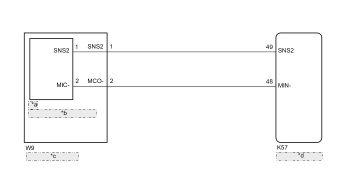
| *a | TM |
| *b | Telephone Microphone Assembly |
| *c | Map Light Assembly |
| *d | Radio Receiver Assembly |
CAUTION / NOTICE / HINT
Note
Depending on the parts that are replaced during vehicle inspection or maintenance, performing initialization, registration or calibration may be needed.
PROCEDURE
-
INSPECT RADIO RECEIVER ASSEMBLY
-
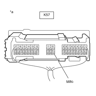
*a Component with harness connected
(Radio Receiver Assembly)
Measure the resistance according to the value(s) in the table below.
Standard Resistance Tester Connection Condition Specified Condition K57-48 (MIN-) - Body ground Always Below 1 Ω Result Proceed to OK NG
NG 
REPLACE RADIO RECEIVER ASSEMBLY Click here
OK 
-
-
CHECK HARNESS AND CONNECTOR (RADIO RECEIVER ASSEMBLY - MAP LIGHT ASSEMBLY)
-
Disconnect the K57 radio receiver assembly connector.
-
Disconnect the W9 map light assembly connector.
-
Measure the resistance according to the value(s) in the table below.
Standard Resistance Tester Connection Condition Specified Condition K57-49 (SNS2) - W9-1 (SNS2) Always Below 1 Ω K57-48 (MIN-) - W9-2 (MCO-) Always Below 1 Ω K57-49 (SNS2) or W9-1 (SNS2) - Body ground Always 10 kΩ or higher K57-48 (MIN-) or W9-2 (MCO-) - Body ground Always 10 kΩ or higher Result Proceed to OK NG
NG
REPAIR OR REPLACE HARNESS OR CONNECTOR
OK
-
-
INSPECT TELEPHONE MICROPHONE ASSEMBLY
-
Remove the telephone microphone assembly.
-
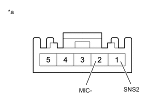
*a Component without harness connected
(Telephone Microphone Assembly)
Measure the resistance according to the value(s) in the table below.
Standard Resistance Tester Connection Condition Specified Condition 1 (SNS2) - 2 (MIC-) Always Below 1 Ω Result Proceed to OK NG
NG
REPLACE TELEPHONE MICROPHONE ASSEMBLY Click here
OK
-
-
INSPECT MAP LIGHT ASSEMBLY
-
Remove the map light assembly.
-
Remove the telephone microphone assembly.
-
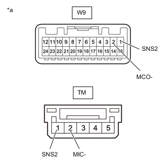
*a Component without harness connected
(Map Light Assembly)
Measure the resistance according to the value(s) in the table below.
Standard Resistance Tester Connection Condition Specified Condition W12-3 (SNS2) - TM-1 (SNS2) Always Below 1 Ω W12-4 (MCO-) - TM-2 (MIC-) Always Below 1 Ω Result Proceed to OK NG
OK
REPLACE RADIO RECEIVER ASSEMBLY Click here
NG
REPLACE MAP LAMP ASSEMBLY Click here
-