NAVIGATION SYSTEM, Diagnostic DTC:B1321, B1322, B1323, B1324, B1325, B1326, B1542, B1563
| DTC Code | DTC Name |
|---|---|
| B1321 | Lost Communication with EMV |
| B1322 | Lost Communication with Display |
| B1323 | Lost Communication with Haptic Device |
| B1324 | Lost Communication with Meter |
| B1325 | Lost Communication with HUD |
| B1326 | Lost Communication with Clock Device (Local-CAN) |
| B1542 | Clock Device Disconnected (Local-CAN) |
| B1563 | Haptic Device Disconnected |
DESCRIPTION
These DTCs are stored when communication between the radio receiver assembly and remote touch (remote operation board), combination meter assembly, combination meter mirror ECU or clock assembly is not possible.
| DTC No. | Detection Item | DTC Detection Condition | Trouble Area |
|---|---|---|---|
| B1321 | Lost Communication with EMV | The components connected via local bus communication do not receive the registration information signal from the radio receiver assembly for 30 seconds or more |
|
| B1322 | Lost Communication with Display | The radio receiver assembly does not receive the registration information from the accessory meter assembly for 30 seconds or more |
|
| B1323 | Lost Communication with Haptic Device | The radio receiver assembly does not receive the registration information signal from the remote touch (remote operation board) for 30 seconds or more |
|
| B1324 | Lost Communication with Meter | After the radio receiver assembly receives a registration information signal, which is sent by the combination meter assembly when the engine switch is turned on (IG), 1 or more times, the radio receiver assembly does not receive the signal for 30 seconds or more |
|
| B1325 | Lost Communication with HUD | After the radio receiver assembly receives a registration information signal, which is sent by the combination meter mirror ECU when the engine switch is turned on (IG), 1 or more times, the radio receiver assembly does not receive the signal for 30 seconds or more |
|
| B1326 | Lost Communication with Clock Device (Local-CAN) | After the radio receiver assembly receives a registration information signal, which is sent by the clock assembly when the engine switch is turned on (IG), 1 or more times, the radio receiver assembly does not receive the signal for 30 seconds or more |
|
| B1542 | Clock Device Disconnected (Local-CAN) | After the engine switch turned on (ACC), the registration information signal from the clock assembly does not match with the registration history information |
|
| B1563 | Haptic Device Disconnected | The remote touch (remote operation board) is/was not connected while the engine switch is/was on (ACC) or on (IG) |
|
Tech Tips
The radio receiver assembly is the master unit.
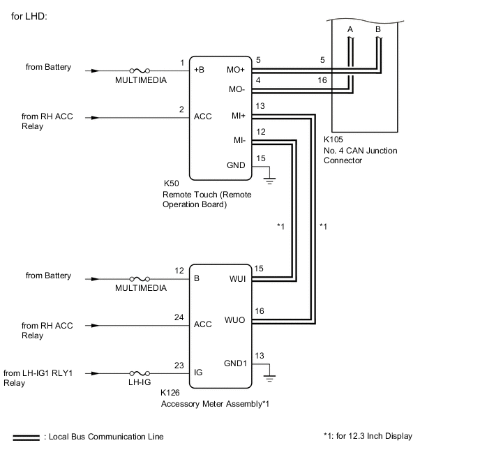
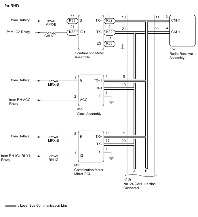
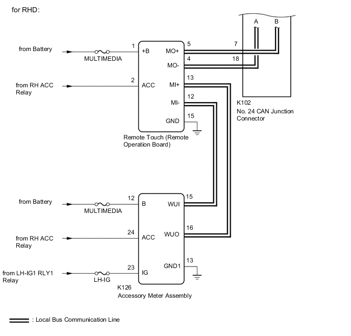
WIRING DIAGRAM

CAUTION / NOTICE / HINT
Note
-
Depending on the parts that are replaced during vehicle inspection or maintenance, performing initialization, registration or calibration may be needed.
-
After turning the engine switch off, waiting time may be required before disconnecting the cable from the negative (-) battery terminal. Therefore, make sure to read the disconnecting the cable from the negative (-) battery terminal notices before proceeding with work.
-
Inspect the fuses for circuits related to this system before performing the following procedure.
PROCEDURE
-
CHECK DTC
-
Clear the DTCs.
Body Electrical > Navigation System > Clear DTCs -
Recheck for DTCs and check that no DTCs are output.
Body Electrical > Navigation System > Trouble CodesResult Result Proceed to All DTCs are not output A All DTCs are output B DTC B1321 is output C DTC B1322 is output D DTCs B1323 or B1563 are output E DTC B1324 is output F DTC B1325 is output G DTCs B1326 or B1542 are output H
A 
USE SIMULATION METHOD TO CHECK Click here
C 
CHECK HARNESS AND CONNECTOR (RADIO RECEIVER ASSEMBLY - CAN JUNCTION CONNECTOR) Click here
D
CHECK HARNESS AND CONNECTOR (ACCESSORY METER ASSEMBLY POWER SOURCE) Click here
E
CHECK HARNESS AND CONNECTOR (REMOTE TOUCH (REMOTE OPERATION BOARD) POWER SOURCE) Click here
F
CHECK HARNESS AND CONNECTOR (COMBINATION METER ASSEMBLY POWER SOURCE) Click here
G
CHECK HARNESS AND CONNECTOR (COMBINATION METER MIRROR ECU POWER SOURCE) Click here
H
CHECK HARNESS AND CONNECTOR (CLOCK ASSEMBLY POWER SOURCE) Click here
B 
-
-
CHECK LOCAL BUS
-
for LHD
-
Disconnect the cable from the negative (-) battery terminal.
-
Measure the resistance according to the value(s) in the table below.
Standard Resistance Tester Connection Condition Specified Condition K105-4 - K105-15 Cable disconnected from negative (-) battery terminal 54 to 69 Ω
-
-
for RHD
-
Disconnect the cable from the negative (-) battery terminal.
-
Measure the resistance according to the value(s) in the table below.
Standard Resistance Tester Connection Condition Specified Condition K102-11 - K102-22 Cable disconnected from negative (-) battery terminal 54 to 69 Ω
Result Result Proceed to OK A NG (Below 54 Ω) B NG (70 Ω or higher) C -
A
USE SIMULATION METHOD TO CHECK Click here
C
CHECK HARNESS AND CONNECTOR (RADIO RECEIVER ASSEMBLY - CAN JUNCTION CONNECTOR) Click here
B
-
-
CHECK HARNESS AND CONNECTOR (RADIO RECEIVER ASSEMBLY - CAN JUNCTION CONNECTOR)
-
for LHD
-
Disconnect the cable from the negative (-) battery terminal.
-
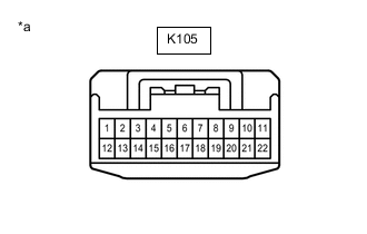
*a Front view of wire harness connector
(to No. 4 CAN Junction Connector)
Disconnect the K105 No. 4 CAN junction connector.
-
Connect the K57 radio receiver assembly connector.
-
Measure the resistance according to the value(s) in the table below.
Standard Resistance Tester Connection Condition Specified Condition K105-4 - K105-15 Cable disconnected from negative (-) battery terminal 108 to 132 Ω
-
-
for RHD
-
Disconnect the cable from the negative (-) battery terminal.
-

*a Front view of wire harness connector
(to No. 24 CAN Junction Connector)
Disconnect the K102 No. 24 CAN junction connector.
-
Connect the K57 radio receiver assembly connector.
-
Measure the resistance according to the value(s) in the table below.
Standard Resistance Tester Connection Condition Specified Condition K102-11 - K102-22 Cable disconnected from negative (-) battery terminal 108 to 132 Ω
Result Proceed to OK NG -
NG
CHECK HARNESS AND CONNECTOR (RADIO RECEIVER ASSEMBLY - CAN JUNCTION CONNECTOR) Click here
OK
-
-
CHECK HARNESS AND CONNECTOR (REMOTE TOUCH (REMOTE OPERATION BOARD) - CAN JUNCTION CONNECTOR)
-
for LHD
-
Disconnect the cable from the negative (-) battery terminal.
-
*a Front view of wire harness connector
(to No. 4 CAN Junction Connector)
Disconnect the K105 No. 4 CAN junction connector.
-
Connect the K50 remote touch (remote operation board) connector.
-
Measure the resistance according to the value(s) in the table below.
Standard Resistance Tester Connection Condition Specified Condition K105-5 - K105-16 Cable disconnected from negative (-) battery terminal 108 to 132 Ω
-
-
for RHD
-
Disconnect the cable from the negative (-) battery terminal.
-
*a Front view of wire harness connector
(to No. 24 CAN Junction Connector)
Disconnect the K102 No. 24 CAN junction connector.
-
Connect the K50 remote touch (remote operation board) connector.
-
Measure the resistance according to the value(s) in the table below.
Standard Resistance Tester Connection Condition Specified Condition K102-7 - K102-18 Cable disconnected from negative (-) battery terminal 108 to 132 Ω
Result Proceed to OK NG -
NG
CHECK HARNESS AND CONNECTOR (COMBINATION METER ASSEMBLY - CAN JUNCTION CONNECTOR) Click here
OK
-
-
CHECK HARNESS AND CONNECTOR (COMBINATION METER ASSEMBLY - CAN JUNCTION CONNECTOR)
-
for LHD
-
Disconnect the cable from the negative (-) battery terminal.
-
*a Front view of wire harness connector
(to No. 4 CAN Junction Connector)
Disconnect the K105 No. 4 CAN junction connector.
-
Connect the K32 combination meter assembly connector.
-
Measure the resistance according to the value(s) in the table below.
Standard Resistance Tester Connection Condition Specified Condition K105-3 - K105-14 Cable disconnected from negative (-) battery terminal 200 Ω or higher
-
-
for RHD
-
Disconnect the cable from the negative (-) battery terminal.
-
*a Front view of wire harness connector
(to No. 24 CAN Junction Connector)
Disconnect the K102 No. 24 CAN junction connector.
-
Connect the K32 combination meter assembly connector.
-
Measure the resistance according to the value(s) in the table below.
Standard Resistance Tester Connection Condition Specified Condition K102-10 - K102-21 Cable disconnected from negative (-) battery terminal 200 Ω or higher
Result Proceed to OK NG -
NG
CHECK HARNESS AND CONNECTOR (REMOTE TOUCH (REMOTE OPERATION BOARD) - ACCESSORY METER ASSEMBLY) Click here
OK
-
-
CHECK HARNESS AND CONNECTOR (COMBINATION METER MIRROR ECU - CAN JUNCTION CONNECTOR)
-
for LHD
-
Disconnect the cable from the negative (-) battery terminal.
-
*a Front view of wire harness connector
(to No. 4 CAN Junction Connector)
Disconnect the K105 No. 4 CAN junction connector.
-
Connect the M1 combination meter mirror ECU connector.
-
Measure the resistance according to the value(s) in the table below.
Standard Resistance Tester Connection Condition Specified Condition K105-2 - K105-13 Cable disconnected from negative (-) battery terminal 200 Ω or higher
-
-
for RHD
-
Disconnect the cable from the negative (-) battery terminal.
-
*a Front view of wire harness connector
(to No. 24 CAN Junction Connector)
Disconnect the K102 No. 24 CAN junction connector.
-
Connect the M1 combination meter mirror ECU connector.
-
Measure the resistance according to the value(s) in the table below.
Standard Resistance Tester Connection Condition Specified Condition K102-9 - K102-20 Cable disconnected from negative (-) battery terminal 200 Ω or higher
Result Proceed to OK NG -
NG
CHECK HARNESS AND CONNECTOR (COMBINATION METER MIRROR ECU - CAN JUNCTION CONNECTOR) Click here
OK
-
-
CHECK HARNESS AND CONNECTOR (CLOCK ASSEMBLY - CAN JUNCTION CONNECTOR)
-
for LHD
-
Disconnect the cable from the negative (-) battery terminal.
-
*a Front view of wire harness connector
(to No. 4 CAN Junction Connector)
Disconnect the K105 No. 4 CAN junction connector.
-
Connect the K55 clock assembly connector.
-
Measure the resistance according to the value(s) in the table below.
Standard Resistance Tester Connection Condition Specified Condition K105-1 - K105-12 Cable disconnected from negative (-) battery terminal 200 Ω or higher
-
-
for RHD
-
Disconnect the cable from the negative (-) battery terminal.
-
*a Front view of wire harness connector
(to No. 24 CAN Junction Connector)
Disconnect the K102 No. 24 CAN junction connector.
-
Connect the K55 clock assembly connector.
-
Measure the resistance according to the value(s) in the table below.
Standard Resistance Tester Connection Condition Specified Condition K102-8 - K102-19 Cable disconnected from negative (-) battery terminal 200 Ω or higher
Result Result Proceed to OK (for LHD) A OK (for RHD) B NG C -
A
REPLACE NO. 4 CAN JUNCTION CONNECTOR
B
REPLACE NO. 24 CAN JUNCTION CONNECTOR
C
-
-
CHECK HARNESS AND CONNECTOR (CLOCK ASSEMBLY - CAN JUNCTION CONNECTOR)
-
for LHD
-
Disconnect the cable from the negative (-) battery terminal.
-
Disconnect the K55 clock assembly connector.
-
Connect the K105 No. 4 CAN junction connector.
-
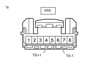
*a Front view of wire harness connector
(to Clock Assembly)
Measure the resistance according to the value(s) in the table below.
Standard Resistance Tester Connection Condition Specified Condition K55-5 (TX+1) - K55-6 (TX-1) Cable disconnected from negative (-) battery terminal 54 to 69 Ω
-
-
for RHD
-
Disconnect the cable from the negative (-) battery terminal.
-
Disconnect the K55 clock assembly connector.
-
Disconnect the K102 No. 24 CAN junction connector.
-
*a Front view of wire harness connector
(to Clock Assembly)
Measure the resistance according to the value(s) in the table below.
Standard Resistance Tester Connection Condition Specified Condition K55-5 (TX+1) - K55-6 (TX-1) Cable disconnected from negative (-) battery terminal 54 to 69 Ω
Result Proceed to OK NG -
OK
REPLACE CLOCK ASSEMBLY Click here
NG
REPAIR OR REPLACE HARNESS OR CONNECTOR
-
-
CHECK HARNESS AND CONNECTOR (COMBINATION METER MIRROR ECU - CAN JUNCTION CONNECTOR)
-
for LHD
-
Disconnect the cable from the negative (-) battery terminal.
-
Disconnect the M1 combination meter mirror ECU connector.
-
Connect the K105 No. 4 CAN junction connector.
-
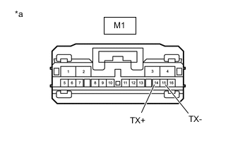
*a Front view of wire harness connector
(to Combination Meter Mirror ECU)
Measure the resistance according to the value(s) in the table below.
Standard Resistance Tester Connection Condition Specified Condition M1-14 (TX+) - M1-15 (TX-) Cable disconnected from negative (-) battery terminal 54 to 69 Ω
-
-
for RHD
-
Disconnect the cable from the negative (-) battery terminal.
-
Disconnect the M1 combination meter mirror ECU connector.
-
Connect the K102 No. 24 CAN junction connector.
-
*a Front view of wire harness connector
(to Combination Meter Mirror ECU)
Measure the resistance according to the value(s) in the table below.
Standard Resistance Tester Connection Condition Specified Condition M1-14 (TX+) - M1-15 (TX-) Cable disconnected from negative (-) battery terminal 54 to 69 Ω
Result Proceed to OK NG -
OK
REPLACE COMBINATION METER MIRROR ECU Click here
NG
REPAIR OR REPLACE HARNESS OR CONNECTOR
-
-
CHECK HARNESS AND CONNECTOR (REMOTE TOUCH (REMOTE OPERATION BOARD) - ACCESSORY METER ASSEMBLY)
-
for LHD
-
Disconnect the cable from the negative (-) battery terminal.
-
Disconnect the K50 remote touch (remote operation board) connector.
-
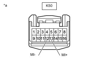
*a Front view of wire harness connector
(to Remote Touch (Remote Operation Board))
Connect the K105 No. 4 CAN junction connector.
-
Measure the resistance according to the value(s) in the table below.
Standard Resistance Tester Connection Condition Specified Condition K50-13 (MI+) - K50-12 (MI-) Cable disconnected from negative (-) battery terminal 200 Ω or higher
-
-
for RHD
-
Disconnect the cable from the negative (-) battery terminal.
-
Disconnect the K50 remote touch (remote operation board) connector.
-
*a Front view of wire harness connector
(to Remote Touch (Remote Operation Board))
Connect the K102 No. 24 CAN junction connector.
-
Measure the resistance according to the value(s) in the table below.
Standard Resistance Tester Connection Condition Specified Condition K50-13 (MI+) - K50-12 (MI-) Cable disconnected from negative (-) battery terminal 200 Ω or higher
Result Proceed to OK NG -
NG
CHECK HARNESS AND CONNECTOR (ACCESSORY METER ASSEMBLY - REMOTE TOUCH (REMOTE OPERATION BOARD)) Click here
OK
-
-
CHECK HARNESS AND CONNECTOR (REMOTE TOUCH (REMOTE OPERATION BOARD) - CAN JUNCTION CONNECTOR)
-
for LHD
-
Disconnect the cable from the negative (-) battery terminal.
-
Disconnect the K50 remote touch (remote operation board) connector.
-
Connect the K105 No. 4 CAN junction connector.
-
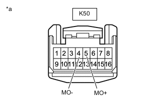
*a Front view of wire harness connector
(to Remote Touch (Remote Operation Board))
Measure the resistance according to the value(s) in the table below.
Standard Resistance Tester Connection Condition Specified Condition K50-5 (MO+) - K50-4 (MO-) Cable disconnected from negative (-) battery terminal 108 to 132 Ω
-
-
for RHD
-
Disconnect the cable from the negative (-) battery terminal.
-
Disconnect the K50 remote touch (remote operation board) connector.
-
Connect the K102 No. 24 CAN junction connector.
-
*a Front view of wire harness connector
(to Remote Touch (Remote Operation Board))
Measure the resistance according to the value(s) in the table below.
Standard Resistance Tester Connection Condition Specified Condition K50-5 (MO+) - K50-4 (MO-) Cable disconnected from negative (-) battery terminal 108 to 132 Ω
Result Proceed to OK NG -
OK
REPLACE REMOTE TOUCH (REMOTE OPERATION BOARD) Click here
NG
REPAIR OR REPLACE HARNESS OR CONNECTOR
-
-
CHECK HARNESS AND CONNECTOR (ACCESSORY METER ASSEMBLY - REMOTE TOUCH (REMOTE OPERATION BOARD))
-
Disconnect the cable from the negative (-) battery terminal.
-
Disconnect the K126 accessory meter assembly connector.
-
Connect the K50 remote touch (remote operation board) connector.
-
Connect the K105 No. 4 CAN junction connector.
-
*a Front view of wire harness connector
(to Accessory Meter Assembly)
Measure the resistance according to the value(s) in the table below.
Standard Resistance Tester Connection Condition Specified Condition K126-16 (WUO) - K126-15 (MUI) Cable disconnected from negative (-) battery terminal 54 to 69 Ω Result Proceed to OK NG
OK
REPLACE ACCESSORY METER ASSEMBLY Click here
NG
REPAIR OR REPLACE HARNESS OR CONNECTOR
-
-
CHECK HARNESS AND CONNECTOR (COMBINATION METER ASSEMBLY - CAN JUNCTION CONNECTOR)
-
for LHD
-
Disconnect the cable from the negative (-) battery terminal.
-
Disconnect the K32 combination meter assembly connector.
-
*a Front view of wire harness connector
(to Combination Meter Assembly)
Connect the K105 No. 4 CAN junction connector.
-
Measure the resistance according to the value(s) in the table below.
Standard Resistance Tester Connection Condition Specified Condition K32-3(TX+) - K32-2(TX-) Cable disconnected from negative (-) battery terminal 108 to 132 Ω
-
-
for RHD
-
Disconnect the cable from the negative (-) battery terminal.
-
Disconnect the K32 combination meter assembly connector.
-
*a Front view of wire harness connector
(to Combination Meter Assembly)
Connect the K102 No. 24 CAN junction connector.
-
Measure the resistance according to the value(s) in the table below.
Standard Resistance Tester Connection Condition Specified Condition K32-3(TX+) - K32-2(TX-) Cable disconnected from negative (-) battery terminal 108 to 132 Ω
Result Proceed to OK NG -
OK
REPLACE COMBINATION METER ASSEMBLY Click here
NG
REPAIR OR REPLACE HARNESS OR CONNECTOR
-
-
CHECK HARNESS AND CONNECTOR (RADIO RECEIVER ASSEMBLY - CAN JUNCTION CONNECTOR)
-
for LHD
-
Disconnect the cable from the negative (-) battery terminal.
-
Disconnect the K57 radio receiver assembly connector.
-
*a Front view of wire harness connector
(to Radio Receiver Assembly)
Connect the K105 No. 4 CAN junction connector.
-
Measure the resistance according to the value(s) in the table below.
Standard Resistance Tester Connection Condition Specified Condition K57-3(CNH1) - K57-4(CNL1) Cable disconnected from negative (-) battery terminal 108 to 132 Ω
-
-
for RHD
-
Disconnect the cable from the negative (-) battery terminal.
-
Disconnect the K57 radio receiver assembly connector.
-
*a Front view of wire harness connector
(to Radio Receiver Assembly)
Connect the K102 No. 24 CAN junction connector.
-
Measure the resistance according to the value(s) in the table below.
Standard Resistance Tester Connection Condition Specified Condition K57-3(CNH1) - K57-4(CNL1) Cable disconnected from negative (-) battery terminal 108 to 132 Ω
Result Proceed to OK NG -
OK
REPLACE RADIO RECEIVER ASSEMBLY Click here
NG
REPAIR OR REPLACE HARNESS OR CONNECTOR
-
-
CHECK HARNESS AND CONNECTOR (RADIO RECEIVER ASSEMBLY - CAN JUNCTION CONNECTOR)
-
for LHD
-
Disconnect the cable from the negative (-) battery terminal.
-
Disconnect the K57 radio receiver assembly connector.
-
Connect the K105 No. 4 CAN junction connector.
-
*a Front view of wire harness connector
(to Radio Receiver Assembly)
Measure the resistance according to the value(s) in the table below.
Standard Resistance Tester Connection Condition Specified Condition K57-3 (CNH1) - K57-4 (CNL1) Cable disconnected from negative (-) battery terminal 108 to 132 Ω
-
-
for RHD
-
Disconnect the cable from the negative (-) battery terminal.
-
Disconnect the K57 radio receiver assembly connector.
-
Connect the K102 No. 24 CAN junction connector.
-
*a Front view of wire harness connector
(to Radio Receiver Assembly)
Measure the resistance according to the value(s) in the table below.
Standard Resistance Tester Connection Condition Specified Condition K57-3 (CNH1) - K57-4 (CNL1) Cable disconnected from negative (-) battery terminal 108 to 132 Ω
Result Proceed to OK NG -
OK
REPLACE RADIO RECEIVER ASSEMBLY Click here
NG
-
-
CHECK HARNESS AND CONNECTOR (RADIO RECEIVER ASSEMBLY - CAN JUNCTION CONNECTOR)
-
for LHD
-
Disconnect the cable from the negative (-) battery terminal.
-
*a Front view of wire harness connector
(to No. 4 CAN Junction Connector)
Disconnect the K105 No. 4 CAN junction connector.
-
Connect the K57 radio receiver assembly connector.
-
Measure the resistance according to the value(s) in the table below.
Standard Resistance Tester Connection Condition Specified Condition K105-1 - K105-12 Cable disconnected from negative (-) battery terminal 200 Ω or higher
-
-
for RHD
-
Disconnect the cable from the negative (-) battery terminal.
-
*a Front view of wire harness connector
(to No. 24 CAN Junction Connector)
Disconnect the K102 No. 24 CAN junction connector.
-
Connect the K57 radio receiver assembly connector.
-
Measure the resistance according to the value(s) in the table below.
Standard Resistance Tester Connection Condition Specified Condition K102-8 - K102-19 Cable disconnected from negative (-) battery terminal 200 Ω or higher
Result Result Proceed to OK (for LHD) A OK (for RHD) B NG C -
A
REPLACE NO. 4 CAN JUNCTION CONNECTOR
B
REPLACE NO. 24 CAN JUNCTION CONNECTOR
C
REPAIR OR REPLACE HARNESS OR CONNECTOR
-
-
CHECK HARNESS AND CONNECTOR (RADIO RECEIVER ASSEMBLY - CAN JUNCTION CONNECTOR)
-
Disconnect the cable from the negative (-) battery terminal.
-
Disconnect the K57 radio receiver assembly connector.
-
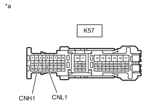
*a Front view of wire harness connector
(to Radio Receiver Assembly)
Measure the resistance according to the value(s) in the table below.
Standard Resistance Tester Connection Condition Specified Condition K57-3 (CNH1) - K57-4 (CNL1) Cable disconnected from negative (-) battery terminal 108 to 132 Ω Result Proceed to OK NG
OK
REPLACE RADIO RECEIVER ASSEMBLY Click here
NG
REPAIR OR REPLACE HARNESS OR CONNECTOR
-
-
CHECK HARNESS AND CONNECTOR (ACCESSORY METER ASSEMBLY POWER SOURCE)
-
Disconnect the accessory meter assembly connector.
-
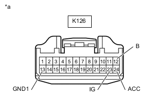
*a Front view of wire harness connector
(to Accessory Meter Assembly)
Measure the resistance according to the value(s) in the table below.
Standard Resistance Tester Connection Condition Specified Condition K126-13 (GND1) - Body ground Always Below 1 Ω -
Measure the voltage according to the value(s) in the table below.
Standard Voltage Tester Connection Condition Specified Condition K126-12 (B) - Body ground Engine switch off 11 to 14 V K126-24 (ACC) - Body ground Engine switch on (ACC) 11 to 14 V K126-23 (IG) - Body ground Engine switch on (IG) 11 to 14 V Result Proceed to OK NG
NG
REPAIR OR REPLACE HARNESS OR CONNECTOR
OK
-
-
CHECK HARNESS AND CONNECTOR (ACCESSORY METER ASSEMBLY - REMOTE TOUCH (REMOTE OPERATION BOARD))
-
Disconnect the cable from the negative (-) battery terminal.
-
Disconnect the accessory meter assembly connector.
-

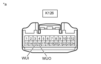
*a Front view of wire harness connector
(to Accessory Meter Assembly)
Measure the resistance according to the value(s) in the table below.
Standard Resistance Tester Connection Condition Specified Condition K126-16 (WUO) - K126-15 (WUI) Cable disconnected from negative (-) battery terminal 54 to 69 Ω Result Proceed to OK NG
OK
REPLACE ACCESSORY METER ASSEMBLY Click here
NG
REPAIR OR REPLACE HARNESS OR CONNECTOR
-
-
CHECK HARNESS AND CONNECTOR (REMOTE TOUCH (REMOTE OPERATION BOARD) POWER SOURCE)
-
Disconnect the remote touch (remote operation board) connector.
-
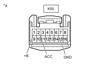
*a Front view of wire harness connector
(to Remote Touch (Remote Operation Board))
Measure the resistance according to the value(s) in the table below.
Standard Resistance Tester Connection Condition Specified Condition K50-15 (GND) - Body ground Always Below 1 Ω -
Measure the voltage according to the value(s) in the table below.
Standard Voltage Tester Connection Switch Condition Specified Condition K50-1 (+B) - Body ground Always 11 to 14 V K50-2 (ACC) - Body ground Engine switch on (ACC) 11 to 14 V Result Proceed to OK NG
NG
REPAIR OR REPLACE HARNESS OR CONNECTOR
OK
-
-
CHECK HARNESS AND CONNECTOR (REMOTE TOUCH (REMOTE OPERATION BOARD) - CAN JUNCTION CONNECTOR)
-
Disconnect the cable from the negative (-) battery terminal.
-
Disconnect the remote touch (remote operation board) connector.
-
*a Front view of wire harness connector
(to Remote Touch (Remote Operation Board))
Measure the resistance according to the value(s) in the table below.
Standard Resistance Tester Connection Condition Specified Condition K50-5 (MO+) - K50-4 (MO-) Cable disconnected from negative (-) battery terminal 108 to 132 Ω Result Proceed to OK NG
OK
REPLACE REMOTE TOUCH (REMOTE OPERATION BOARD) Click here
NG
REPAIR OR REPLACE HARNESS OR CONNECTOR
-
-
CHECK HARNESS AND CONNECTOR (COMBINATION METER ASSEMBLY POWER SOURCE)
-
Disconnect the K33 combination meter assembly connector.
-
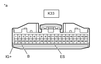
*a Front view of wire harness connector
(to Combination Meter Assembly)
Measure the resistance according to the value(s) in the table below.
Standard Resistance Tester Connection Condition Specified Condition K33-31 (ES) - Body ground Always Below 1 Ω -
Measure the voltage according to the value(s) in the table below.
Standard Voltage Tester Connection Switch Condition Specified Condition K33-22 (B) - Body ground Always 11 to 14 V K33-21 (IG+) - Body ground Engine switch on (IG) 11 to 14 V Result Proceed to OK NG
NG
REPAIR OR REPLACE HARNESS OR CONNECTOR
OK
-
-
CHECK HARNESS AND CONNECTOR (COMBINATION METER ASSEMBLY - CAN JUNCTION CONNECTOR)
-
Disconnect the cable from the negative (-) battery terminal.
-
Disconnect the combination meter assembly connector.
-
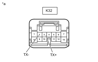
*a Front view of wire harness connector
(to Combination Meter Mirror ECU)
Measure the resistance according to the value(s) in the table below.
Standard Resistance Tester Connection Condition Specified Condition K32-3 (TX+) - K32-2 (TX-) Cable disconnected from negative (-) battery terminal 54 to 69 Ω Result Proceed to OK NG
OK
REPLACE COMBINATION METER ASSEMBLY Click here
NG
REPAIR OR REPLACE HARNESS OR CONNECTOR
-
-
CHECK HARNESS AND CONNECTOR (COMBINATION METER MIRROR ECU POWER SOURCE)
-
Disconnect the combination meter mirror ECU connector.
-
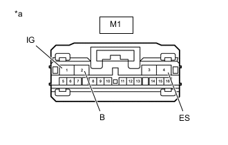
*a Front view of wire harness connector
(to Combination Meter Mirror ECU)
Measure the resistance according to the value(s) in the table below.
Standard Resistance Tester Connection Condition Specified Condition M1-6 (ES) - Body ground Always Below 1 Ω -
Measure the voltage according to the value(s) in the table below.
Standard Voltage Tester Connection Switch Condition Specified Condition M1-2 (B) - Body ground Always 11 to 14 V M1-1 (IG) - Body ground Engine switch on (IG) 11 to 14 V Result Proceed to OK NG
NG
REPAIR OR REPLACE HARNESS OR CONNECTOR
OK
-
-
CHECK HARNESS AND CONNECTOR (COMBINATION METER MIRROR ECU - CAN JUNCTION CONNECTOR)
-
Disconnect the cable from the negative (-) battery terminal.
-
Disconnect the combination meter mirror ECU connector.
-
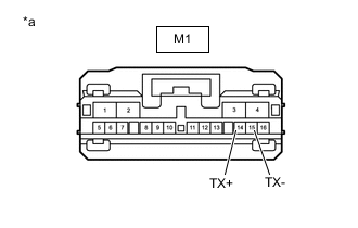
*a Front view of wire harness connector
(to Combination Meter Mirror ECU)
Measure the resistance according to the value(s) in the table below.
Standard Resistance Tester Connection Condition Specified Condition M1-14 (TX+) - M1-15 (TX-) Cable disconnected from negative (-) battery terminal 54 to 69 Ω Result Proceed to OK NG
OK
REPLACE COMBINATION METER MIRROR ECU Click here
NG
REPAIR OR REPLACE HARNESS OR CONNECTOR
-
-
CHECK HARNESS AND CONNECTOR (CLOCK ASSEMBLY POWER SOURCE)
-
Disconnect the clock assembly connector.
-
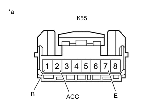
*a Front view of wire harness connector
(to Clock Assembly)
Measure the resistance according to the value(s) in the table below.
Standard Resistance Tester Connection Condition Specified Condition K55-7 (E) - Body ground Always Below 1 Ω -
Measure the voltage according to the value(s) in the table below.
Standard Voltage Tester Connection Switch Condition Specified Condition K55-1 (B) - Body ground Always 11 to 14 V K55-2 (ACC) - Body ground Engine switch on (ACC) 11 to 14 V Result Proceed to OK NG
NG
REPAIR OR REPLACE HARNESS OR CONNECTOR
OK
-
-
CHECK HARNESS AND CONNECTOR (CLOCK ASSEMBLY - CAN JUNCTION CONNECTOR)
-
Disconnect the cable from the negative (-) battery terminal.
-
Disconnect the clock assembly connector.
-

*a Front view of wire harness connector
(to Clock Assembly)
Measure the resistance according to the value(s) in the table below.
Standard Resistance Tester Connection Condition Specified Condition K55-5 (TX1+) - K55-6 (TX1-) Cable disconnected from negative (-) battery terminal 54 to 69 Ω Result Proceed to OK NG
OK
REPLACE CLOCK ASSEMBLY Click here
NG
REPAIR OR REPLACE HARNESS OR CONNECTOR
-