ASC SYSTEM Power Source Circuit
DESCRIPTION
This is the power source circuit for the stereo component equalizer assembly. This circuit provides two types of power source; one is a constant power source, and the other is an IG power source.
WIRING DIAGRAM
-
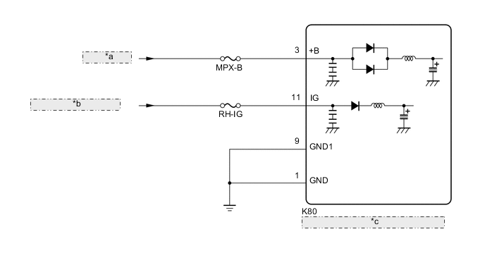
for LHD *a from Battery *b from RH-IG1 RLY1 Relay *c Stereo Component Equalizer Assembly -
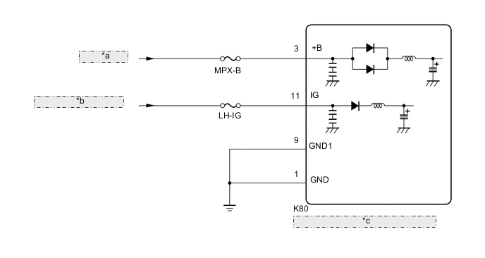
for RHD *a from Battery *b from LH-IG1 RLY1 Relay *c Stereo Component Equalizer Assembly
CAUTION / NOTICE / HINT
Note
Inspect the fuses for circuits related to this system before performing the following procedure.
PROCEDURE
-
CHECK HARNESS AND CONNECTOR (POWER SOURCE - STEREO COMPONENT EQUALIZER ASSEMBLY)
-
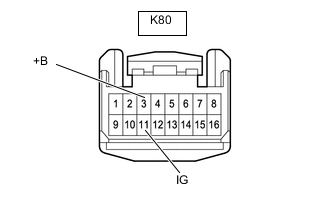
Disconnect the K80 stereo component equalizer assembly connector.
-
Measure the voltage according to the value(s) in the table below.
Standard Voltage Tester Connection Condition Specified Condition K80-3 (+B) - Body ground Always 11 to 14 V K80-11 (IG) - Body ground Engine switch off Below 1 V K80-11 (IG) - Body ground Engine switch on (IG) 11 to 14 V Result Proceed to OK NG
NG 
REPAIR OR REPLACE HARNESS OR CONNECTOR
OK 
-
-
CHECK HARNESS AND CONNECTOR (BODY GROUND - STEREO COMPONENT EQUALIZER ASSEMBLY)
-
Measure the resistance according to the value(s) in the table below.
Standard Resistance Tester Connection Condition Specified Condition K80-1 (GND) - Body ground Always Below 1 Ω K80-9 (GND1) - Body ground Always Below 1 Ω Result Proceed to OK NG
OK
PROCEED TO NEXT SUSPECTED AREA SHOWN IN PROBLEM SYMPTOMS TABLE Click here
NG
REPAIR OR REPLACE HARNESS OR CONNECTOR
-