ASC SYSTEM Main Switch Circuit
DESCRIPTION
The stereo component equalizer assembly receives signals from the vehicle sound switch. The ASC system can be turned on and off by operating the vehicle sound switch.
WIRING DIAGRAM
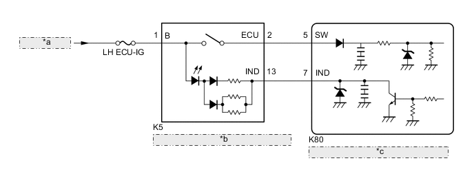
| *a | from LH-IG1 RLY1 Relay |
| *b | Vehicle Sound Switch (Integration Control and Panel Assembly) |
| *c | Stereo Component Equalizer Assembly |
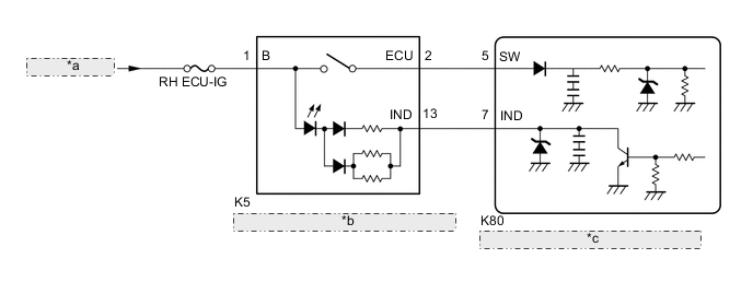
| *a | from RH-IG1 RLY1 Relay |
| *b | Vehicle Sound Switch (Integration Control and Panel Assembly) |
| *c | Stereo Component Equalizer Assembly |
CAUTION / NOTICE / HINT
Note
Inspect the fuses for circuits related to this system before performing the following procedure.
PROCEDURE
-
READ VALUE USING GTS
-
Connect the GTS to the DLC3.
-
Turn the engine switch on (IG).
-
Turn the GTS on.
-
Enter the following menus: Body Electrical / ASC / Data List.
-
Read the Data List according to the display on the GTS.
Body Electrical > ASC > Data ListTester Display Measurement Item Range Normal Condition Diagnostic Note ASC Switch Vehicle sound switch on/off status OFF or ON OFF: Vehicle sound switch off
ON: Vehicle sound switch on
-
Body Electrical > ASC > Data ListTester Display ASC Switch OK Normal conditions listed above are displayed. Result Proceed to OK NG
OK 
PROCEED TO NEXT SUSPECTED AREA SHOWN IN PROBLEM SYMPTOMS TABLE
NG 
-
-
INSPECT VEHICLE SOUND SWITCH (INTEGRATION CONTROL AND PANEL ASSEMBLY)
-
Check the vehicle sound switch on/off operation.
-
Remove the vehicle sound switch (integration control and panel assembly).
-
Inspect the vehicle sound switch (integration control and panel assembly).
Result Proceed to OK NG -
NG
REPLACE VEHICLE SOUND SWITCH (INTEGRAETION CONTROL AND PANEL ASSEMBLY)
OK
-
-
CHECK HARNESS AND CONNECTOR (VEHICLE SOUND SWITCH (INTEGRATION CONTROL AND PANEL ASSEMBLY) - STEREO COMPONENT EQUALIZER ASSEMBLY)
-
Disconnect the K80 stereo component equalizer assembly connector.
-
Measure the resistance according to the value(s) in the table below.
Standard Resistance Tester Connection Condition Specified Condition K5-2 (ECU) - K80-5 (SW) Always Below 1 Ω K5-13 (IND) - K80-7 (IND) Always Below 1 Ω K5-2 (ECU) - Body ground Always 10 kΩ or higher K5-13 (IND) - Body ground Always 10 kΩ or higher Result Proceed to OK NG
OK
REPLACE STEREO COMPONENT EQUALIZER ASSEMBLY
NG
REPAIR OR REPLACE HARNESS OR CONNECTOR
-