AUDIO AND VISUAL SYSTEM(for 8 Inch Display) OPERATION CHECK
-
REMOTE TOUCH SELF CHECK
Note
-
Before entering self-diagnostic mode, make sure there are no obstructions which may interfere with operation of the remote touch switch knob, and that the remote touch switch knob is not stuck.
-
Do not touch the remote touch switch knob except when necessary.
Tech Tips
The following checks can be done via self-diagnostic mode:
-
Remote touch DTC check
-
Switch illumination check
-
Remote touch switch knob position recognition check
-
Switch operation check
-
Remote touch switch knob feedback force check
-
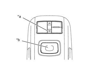
*a Down Switch *b Switch Knob Activate Self-diagnostic Mode
-
While pressing and holding the down switch, turn the engine switch on (ACC) to enter self-diagnostic mode.
-
-
Switch Illumination Check and DTC Check
-
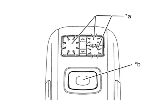
*a Switch Illumination *b Switch Knob Check that the remote touch switch knob automatically moves to the center of the movable area and that the switch illumination blinks.
Tech Tips
During self check mode, all check mode DTCs are stored and the switch illumination blinks at 0.5-second intervals. When the clear conditions for each DTC are met, the DTC is cleared. The switch illumination continues to blink until the self check is complete and all DTCs are cleared.
-
-
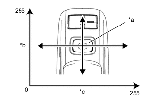
*a Switch Knob *b Longitudinal Axis *c Lateral Axis Remote Touch Switch Knob Position Recognition Check
-
Move the remote touch switch laterally and longitudinally and check that the brightness of the switch illumination changes.
Tech Tips
-
If the brightness of the switch illumination changes according to the position of the remote touch switch knob, the remote touch switch knob position is being correctly recognized.
-
The brightness of the switch illumination changes between 0 and 100% according to the remote touch switch knob coordinates.
-
The remote touch switch coordinates change between 0 and 255 for both the lateral and longitudinal axis.
-
When the remote touch switch knob coordinates of both the lateral and longitudinal axes of the remote touch switch knob are 0, the brightness of the switch illumination will be 0% (off). When the coordinates of both the lateral and longitudinal axis are 255, the brightness of the switch illumination will be 100% (full brightness).
-
-
-
Switch Operation Check
-
Check that the switch illumination turns on at 100% brightness when each switch is pressed while the remote touch switch knob is in the lower left position.
Tech Tips
If the switch illumination turns on at 100% brightness when a switch is pressed, the switch being pressed is operating normally.
-
-
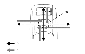
*a Switch Knob *b Movement Direction *c Feedback Force Switch Operation Check
-
Check that the switch illumination turns on at 100% brightness when each switch is pressed while the remote touch switch knob is in the lower left position.
Tech Tips
If the switch illumination turns on at 100% brightness when a switch is pressed, the switch being pressed is operating normally.
-
*a Default Feedback Force Image *b Frame Area *c Icon Area Operate the remote touch switch knob to move the pointer displayed on the multi-display screen and check that remote touch generates feedback according to the pointer display position on the multi-display.
Tech Tips
-
Refer to Remote Touch Outline for further information on the remote touch switch knob feedback force.
-
If the remote touch generates remote touch switch knob feedback force according to the pointer display position, the remote touch is correctly receiving the feedback force setting signal sent from the radio receiver assembly.
-
If the remote touch cannot receive the feedback force setting signal sent from the radio receiver assembly, use the default feedback force image stored in the remote touch to generate feedback force for the remote touch switch knob.
-
-
-
-
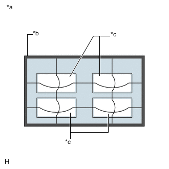
CHECK PANEL & STEERING SWITCH
Tech Tips
-
The radio receiver assembly panel switches and steering switches are checked in the following procedure.
-
Illustrations may differ from the actual vehicle screen depending on the device settings and options. Therefore, some detailed areas may not be shown exactly the same as on the actual vehicle screen.
-
Enter diagnostic mode.
-
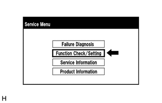
Select "Function Check/Setting" from the "Service Menu" screen.
-
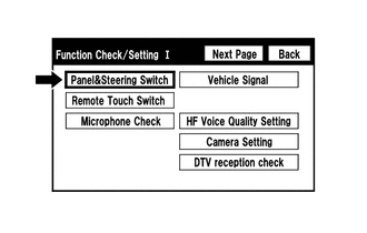
Select "Panel & Steering Switch" from the "Function Check/Setting I" screen.
-
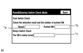
Panel & Steering Switch Check Mode
Screen Description Display Content *a: Switch condition "Pushed" is displayed when any switch is pushed. *b: Number of switches pushed
-
Number of switches pushed at once is displayed.
-
If more than 3 switches are pushed at once, "More than 3" is displayed.
*c: Rotary switch direction Direction of rotary switch is displayed.
-
Operate each switch and check that the switch conditions are correctly displayed.
Note
When the return switch on the remote operation board is pressed and held for 3 seconds or more, diagnostic mode will be canceled.
-
-
-
CHECK REMOTE TOUCH SWITCH
Tech Tips
-
The remote touch switch knob is checked in the following procedure.
-
Illustrations may differ from the actual vehicle screen depending on the device settings and options. Therefore, some detailed areas may not be shown exactly the same as on the actual vehicle screen.
-
Enter diagnostic mode.
-

Select "Function Check/Setting" from the "Service Menu" screen.
-
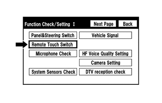
Select "Remote Touch Switch" from the "Function Check/Setting I" screen.
-
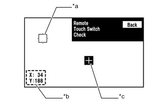
Remote Touch Switch Check
Screen Description Display Content *a: Pointer Displays the location of the pointer. *b: Coordinate
-
Displays the coordinates of the pointer
-
"X" and "Y" indicate the lateral and longitudinal axes
-
Coordinates are displayed by numbers between 0 and 255 for each axis starting from the lower left of the screen
*c: "+" mark Displayed at the location where the pointer was located when the switch knob of the remote touch was pressed.
-
While "Remote Touch Switch Check" is displayed, move the pointer to any blank area of the screen using the remote touch switch knob, and press the switch knob.
Tech Tips
-
The "+" mark is displayed at the pointer position when the switch knob was pressed.
-
Even if the pointer is moved, the "+" mark will remain at the position where the pointer was located when the switch knob was pressed.
-
-
Move the pointer using the remote touch switch knob. When the location of the pointer is changed by moving the switch knob, check that the coordinate values "X" and "Y" change between 0 and 255.
-
-
-
CHECK MICROPHONE
Tech Tips
-
The microphone and microphone input level are checked in the following procedure.
-
Illustrations may differ from the actual vehicle screen depending on the device settings and options. Therefore, some detailed areas may not be shown exactly the same as on the actual vehicle screen.
-
Enter diagnostic mode.
-
Select "Function Check/Setting" from the "Service Menu" screen.
-
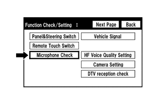
Select "Microphone Check" from the "Function Check/Setting I" screen.
-
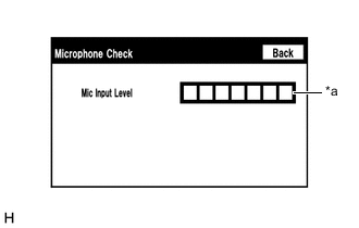
Microphone Check
Screen Description Display Content *a: Microphone input level meter Monitors the microphone input level every 0.1 seconds and displays the results in 8 different levels.
-
When speaking into the microphone, check that the microphone input level meter changes according to the input level.
Tech Tips
The microphone is active at all times when this screen is displayed.
-
-
-
CHECK VEHICLE SIGNAL
Tech Tips
-
Vehicle signals received by the radio receiver assembly are checked in the following procedure.
-
Illustrations may differ from the actual vehicle screen depending on the device settings and options. Therefore, some detailed areas may not be shown exactly the same as on the actual vehicle screen.
-
Enter diagnostic mode.
-
Select "Function Check/Setting" from the "Service Menu" screen.
-
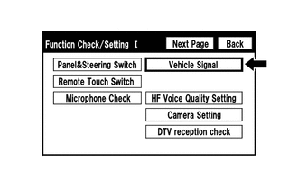
Select "Vehicle Signal" from the "Function Check/Setting I" screen.
-
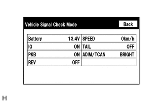
Vehicle Signal Check Mode
Screen Description Display Content Battery Battery voltage is displayed. IG Engine switch ON/OFF state is displayed. PKB Parking brake ON/OFF state is displayed. REV Reverse signal ON/OFF state is displayed. SPEED Vehicle speed is displayed in km/h. TAIL Tail signal (light control switch) ON/OFF state is displayed. ADIM/TCAN Brightness state DIM (with)/BRIGHT (without) is displayed. Tech Tips
-
Only items sending vehicle signals will be displayed.
-
This screen displays vehicle signals received by the radio receiver assembly.
-
This screen is updated once per second.
-
When the "Vehicle Signal Check Mode" screen is displayed, check all the vehicle signal conditions.
-
-
-
CHECK HANDS-FREE VOICE QUALITY SETTING
Tech Tips
-
The hands-free voice of a "Bluetooth" compatible phone can be adjusted using the following procedure.
-
Illustrations may differ from the actual vehicle screen depending on the device settings and options. Therefore, some detailed areas may not be shown exactly the same as on the actual vehicle screen.
-
Enter diagnostic mode.
-
Select "Function Check/Setting" from the "Service Menu" screen.
-
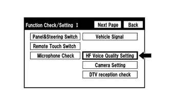
Select "HF Voice Quality Setting" from the "Function Check/Setting I" screen.
-
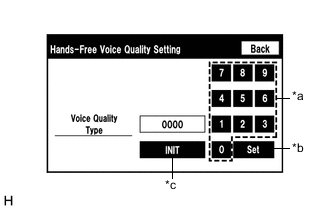
*a Numeric Keypad *b Setting Button *c Reset Button Hands-Free Voice Quality Setting
-
If necessary, refer to the table below to adjust the voice quality type with the numeric keypad.
-
When adjusting the settings, use the number pad on the screen to input the voice quality type according to the table.
Settings Parameter Target Phenomenon Voice Quality Type Positive Effect of Changing Voice Quality Negative Effect of Changing Voice Quality A
(Noise)
The other party hears background noise when listening to your voice. 1000 The amount of background noise the other party hears when listening to your voice is reduced. The volume of voice the other party hears when listening to your voice may temporarily drop. B
(Noise)
The other party hears a lot of background noise when listening to your voice. 2000 The amount of background noise the other party hears when listening to your voice is sharply reduced. The volume of voice the other party hears when listening to your voice may temporarily drop. C
(Echo)
The other party hears weak echoes. 0100 The amount of echo is reduced (low level). Sound quality of the other party deteriorates (low level). D
(Echo)
The other party hears strong echoes. 0200 The amount of echo is reduced (high level). Sound quality of the other party deteriorates (high level). Settings (When Multiple Phenomenon Occurred) Parameter Target Phenomenon Voice Quality Type Positive Effect of Changing Voice Quality Negative Effect of Changing Voice Quality A+C The other party hears background noise and weak echoes when listening to your voice. 1100
-
The amount of background noise the other party hears when listening to your voice is reduced.
-
The amount of echo is reduced (low level).
-
The volume of voice may drop temporarily.
-
Sound quality of the other party deteriorates (low level).
A+D The other party hears background noise and strong echoes when listening to your voice. 1200
-
The amount of background noise the other party hears when listening to your voice is reduced.
-
The amount of echo is reduced (high level).
-
The volume of voice may drop temporarily.
-
Sound quality of the other party deteriorates (high level).
B+C The other party hears a lot of background noise and weak echoes when listening to your voice. 2100
-
The amount of background noise the other party hears when listening to your voice is sharply reduced.
-
The amount of echo is reduced (low level).
-
The volume of voice may drop temporarily.
-
Sound quality of the other party deteriorates (low level).
B+D The other party hears a lot of background noise and strong echoes when listening to your voice. 2200
-
The amount of background noise the other party hears when listening to your voice is sharply reduced.
-
The amount of echo is reduced (high level).
-
The volume of voice may drop temporarily.
-
Sound quality of the other party deteriorates (high level).
Tech Tips
-
The default value is "0000".
-
Settings will be applied when the setting button is selected.
-
If voice quality type values that are not in the table are input, the setting will not be applied and a positive effect may not be gained.
-
If the quality of phone calls decreases due to the changed settings, return the settings to "0000" by selecting "INIT".
-
-
-
-
CHECK DAB RECEPTION (w/ DAB Function)
Tech Tips
-
The reception condition of Digital Audio Broadcast (DAB) can be checked.
-
Illustrations may differ from the actual vehicle screen depending on the device settings and options. Therefore, some detailed areas may not be shown exactly the same as on the actual vehicle screen.
-
Enter diagnostic mode.
-
Select "Function Check/Setting" from the "Service Menu" screen.
-
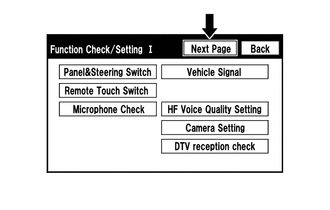
Select "Next Page" from the "Function Check/Setting I" screen.
-
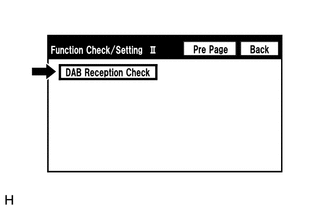
Select "DAB Reception Check" from the "Function Check/Setting II" screen.
-
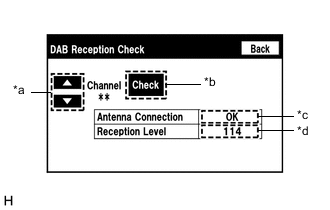
DAB Reception Check
Screen Description Display Content *a: Up or down switch Enables the channel to be changed to the one to be checked. *b: Check/STOP switch
-
Check: Starts checking
-
STOP: Stops checking
*c: Antenna connection check
-
OK: Connected properly
-
NG: Not connected properly
-
-: Not equipped with DAB antenna.
DAB antenna connection status as follows:
*d: DAB Tuner Reception Level Check Result Description
-
111 or more: Font color is black (good reception).
-
110 or less: Font color is red (poor reception).
-
-: Not equipped with DAB antenna.
Displays DAB antenna reception levels as follows:
-
Select the "Check" button to start the DAB reception check.
-
Check the result displayed when the DAB reception check is complete.
-
-
-
CLEAR PASSWORD OF EXPORT/IMPORT MEMORY POINT FUNCTION
Tech Tips
-
This function allows the initialization of a password which was set on the radio receiver assembly when exporting/importing memory points.
-
Illustrations may differ from the actual vehicle screen depending on the device settings and options. Therefore, some detailed areas may not be shown exactly the same as on the actual vehicle screen.
-
Enter diagnostic mode.
-
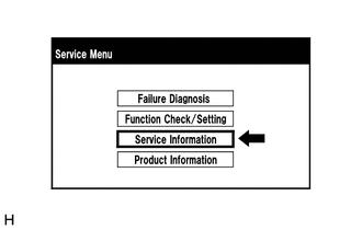
Select "Service Information" from the "Service Menu" screen.
-
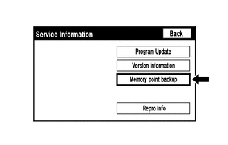
Select "Memory point backup" from the "Service Information" screen.
-
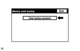
Clear backup password
Tech Tips
Depending on the manufacturer, some component names and versions will be displayed differently.
-
Select "Clear backup password" from the "Memory point backup" screen.
-
-
-
CHECK SPEAKER
Tech Tips
-
This function is used when checking the speaker wiring and whether the speakers are functioning properly.
-
Illustrations may differ from the actual vehicle screen depending on the device settings and options. Therefore, some detailed areas may not be shown exactly the same as on the actual vehicle screen.
-
Turn audio mode on and play any audio source.
Tech Tips
This audio source will be used for the speaker check.
-
Enter diagnostic mode.
-
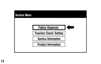
Select "Failure Diagnosis" from the "Service Menu" screen.
-
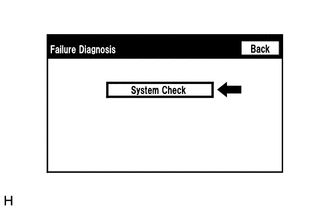
Select "System Check" from the "Failure Diagnosis" screen.
-
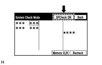
Select "SP Check ON" from the "System Check Mode" screen.
-
Check the speaker wiring and check that the speakers are functioning properly.
Tech Tips
-
Check that each speaker outputs sound from the selected audio source properly.
-
"SP Check OFF" is displayed during the speaker check.
-
Sound can be heard from the speakers around the vehicle in order beginning from a speaker on the front side.
-
More than one speaker may sound simultaneously depending on the speaker wiring.
-
-
Sound stops when any of the following conditions are met:
-
The "SP Check OFF" switch is pressed.
-
The engine switch is turned off.
-
Diagnostic mode is turned off.
-
The screen is changed to another screen.
-
Audio mode is turned off.
-
-
-
CHECK SOFTWARE ERROR HISTORY
Tech Tips
This function is used to check the cause when the radio receiver assembly screen is blacked out.
-
Check software error history.
-
Connect the GTS to the DLC3.
-
Turn the engine switch on (IG).
-
Turn the GTS on.
-
Enter the following menus: Body Electrical / Navigation System / Utility / Software Error History.
Body Electrical > Navigation System > UtilityTester Display Software Error History -
When an item is stored for Software Error History, record it before repairing the radio receiver assembly.
Software Error History Screen Description Error Description Trigger Detail Software Reset Navi Microcomputer Hexadecimal Number Audio Microcomputer CAN Microcomputer No Video Signal Front Monitor Rear Monitor MOST Cold Restart Always Tech Tips
-
Software Error History can store up to 5 history data items. If a new software error occurs when 5 data items have already been stored, the oldest data is cleared and the new data is stored.
-
If an error that is unsupported by the GTS occurs, "-" is displayed for the display items.
-
-
-
Clear software error history.
-
When DTCs are cleared using any of the following operations, Software Error History will be cleared as well.
-
Cleared using the GTS.
-
Cleared using the system check mode screen.
-
Cleared using the unit check mode screen.
-
-
-
-
CHECK OPTICAL DISC ERROR HISTORY
Tech Tips
This function is used to check the cause of an optical disc error.
-
Check optical disc error history.
-
Connect the GTS to the DLC3.
-
Turn the engine switch on (IG).
-
Turn the GTS on.
-
Enter the following menus: Body Electrical / Navigation System / Utility / Optical Disc Error History.
Body Electrical > Navigation System > UtilityTester Display Optical Disc Error History -
When an item is stored for Optical Disc Error History, record it before proceeding with troubleshooting.
Optical Disc Error History Screen Description Display Content Error Type Displays the type of error. Device Displays the malfunctioning device. Date Displays the date and time that the malfunction occurred. "Error Type" Screen Description Error Type Detection Condition Action Read Error When a disc read error occurs. Proceed to next suspected area shown in Problem Symptoms Table.
Disc damaged/upside down/dirty When it is determined that any of the following is the cause of the disc read error:
-
The disc cannot be read.
-
The disc cannot be read because of dirt or scratches.
-
The disc cannot be read because it is inserted upside down.
Cannot determine disc type An unsuitable disc is inserted. DPS error When an error occurs while decoding MP3/WMA/AAC files. Some files are corrupt
-
When MP3/WMA/AAC files cannot be played back because they are unsupported.
-
Even though the file extensions are MP3, WMA or AAC, files cannot be played back because the header information cannot be read.
Some files cannot be found
-
When a disc without music data is played back.
-
When there are no playable MP3/WMA/AAC files.
Copy protection violation When a file with copyright protection that cannot be played back is played back. "Device" Screen Description Device Component DVD-P Radio receiver assembly*1 CD-P Radio receiver assembly*2 R-Seat DVD-P Not available
-
*1: w/ DVD Player
-
*2: w/ CD or VCD Player
Tech Tips
-
Optical Disc Error History can store up to 7 history data items. If a new optical disc error occurs when 7 data items have already been stored, the oldest data is cleared and the new data is stored.
-
If an error that is unsupported by the GTS occurs, "-" or blank is displayed for the display items.
-
-
-
Clear optical disc error history.
-
When DTCs are cleared using any of the following operations, Optical Disc Error History will be cleared as well.
-
Cleared using the GTS.
-
Cleared using the system check mode screen.
-
Cleared using the unit check mode screen.
-
-
-
-
Tech Tips
-
This function is used to detect disconnection of the video devices.
-
In order to inspect the RSE, a disc should be inserted into the radio receiver assembly.
CHECK VIDEO DEVICE CONNECTION CHECK
-
Check Video Device Connection Check.
-
Connect the GTS to the DLC3.
-
Turn the engine switch on (IG).
-
Turn the GTS on.
-
Enter the following menus: Body Electrical / Navigation System / Utility / Video Device Connection Check.
Body Electrical > Navigation System > UtilityTester Display Video Device Connection Check -
When an item is stored for Video Device Connection Check, record it before proceeding with troubleshooting.
Tech Tips
-
DTCs are stored when errors are detected.
-
Depending on the vehicle, some of the items are not displayed on the "Error Detected Image Line (Type)" screen.
Video Device Connection Check Screen Description Error Detected Image Line (Type) Area to be Checked H/U - > Separate Display (GVIF) Digital video signal between the radio receiver assembly and multi-display H/U - > Full RSE (GVIF) Not available RSE - > Seatback Display RH (GVIF) Not available RSE - > Seatback Display LH (GVIF) Not available Rear Camera - > H/U (NTSC) NTSC video signal between the radio receiver assembly and rear television camera assembly IPA/BGM/PVM ECU - > Separate Display (GVIF) Digital video signal between the multi-display IPA/BGM/PVM ECU - > H/U (NTSC) Not available IPA/BGM/PVM ECU - > H/U (GVIF) Not available -
-
-
Clear video device connection check.
-
When DTCs are cleared using any of the following operations, Video Device Connection Check will be cleared as well.
-
Cleared using the GTS.
-
Cleared using the system check mode screen.
-
Cleared using the unit check mode screen.
-
-
-
-
ENFORM RESET PROCEDURE (w/ Enform Function)
-
Duplicate the problem symptom.
-
Check cellular phone compatibility.
-
Check if the cellular phone/vehicle is compatible (Refer to http://www.lexus.com.au/).
-
If the cellular phone is not compatible, recommend to the customer a compatible cellular phone.
-
-
Delete all paired devices from the cellular phone.
-
This procedure varies based on phone model. Contact the service provider or cellular phone manufacturer if assistance is required.
-
-
Remove the Enform app from the phone.
Note
Only perform this step if the customer is present and approves.
-
This procedure varies based on phone model. Contact the service provider or cellular phone manufacturer if assistance is required.
-
-
Reset the phone.
Note
Only perform this step if the customer is present and approves.
-
Turn off the phone and remove the battery for 15 seconds. For instructions on how to reset the cellular devices, refer to the appropriate manufacturer's website.
-
-
Reinstall the Enform app on the phone. (If removed.)
-
This procedure varies based on phone model. Contact the service provider or cellular phone manufacturer if assistance is required.
-
-
Delete all personal data from the radio receiver assembly.
-
Delete all personal data from the radio receiver assembly.
Note
Only perform this step if the customer is present and approves.
Tech Tips
Re-installation of applications must be completed before applications will appear on the radio receiver assembly.
-
-
Disconnect the cable from the negative (-) battery terminal.
Note
After turning the engine switch off, waiting time may be required before disconnecting the cable from the negative (-) battery terminal. Therefore, make sure to read the disconnecting the cable from the negative (-) battery terminal notices before proceeding with work.
-
Record all radio station presets.
-
Disconnect the cable from the negative (-) battery terminal and leave it disconnected for 2 minutes.
-
-
Check if the problem symptom has been repaired.
-