TILT AND TELESCOPIC MANUAL SWITCH REMOVAL
CAUTION / NOTICE / HINT
The necessary procedures (adjustment, calibration, initialization, or registration) that must be performed after parts are removed, installed, or replaced during the tilt and telescopic switch removal/installation are shown below.
| Replacement Part or Procedure | Necessary Procedure | Effect/Inoperative when not Performed | Link |
|---|---|---|---|
| Disconnect cable from negative battery terminal | Memorize steering angle neutral point | Parking assist monitor system | |
| Lane departure alert system (w/ Steering Control) | |||
| Pre-crash safety system | |||
| Adaptive high beam system | |||
| Reset power trunk lid | Power trunk lid system |
Note
-
Do not replace the spiral cable with sensor sub-assembly with the battery connected and the engine switch on (IG).
-
Do not rotate the spiral cable with sensor sub-assembly without the steering wheel assembly installed, with the battery connected and the engine switch on (IG).
-
Ensure that the steering wheel assembly is installed and aligned straight when inspecting the steering sensor.
PROCEDURE
-
CHANGE POWER TILT AND POWER TELESCOPIC STEERING COLUMN SYSTEM SETTINGS
-
ALIGN FRONT WHEELS FACING STRAIGHT AHEAD
-
REMOVE HORN BUTTON ASSEMBLY
-
REMOVE STEERING WHEEL ASSEMBLY
-
REMOVE STEERING COLUMN COVER (for Lower Side)
-
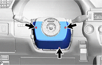
Remove the 3 screws.
-

Push Area 
Remove in this Direction (1) 
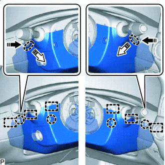
Remove in this Direction (2) Press in, in the direction shown by the arrow (1) in the illustration, and disengage the claws.
-
Pull out in the direction indicated by the arrow (2) in the illustration, disengage the claws and guides to remove the steering column cover (lower).
-
-
REMOVE TILT AND TELESCOPIC SWITCH
-
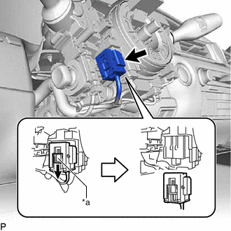
*a Slider Slide the slider to release the lock, and then disconnect the yellow airbag connector from the spiral cable with sensor sub-assembly.
Note
When disconnecting any airbag connector, take care not to damage the airbag wire harness.
-
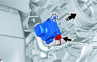
Remove in this Direction Disconnect the tilt and telescopic connector from the tilt and telescopic switch.
-
Disengage the claw and pull out the tilt and telescopic switch.
-