HEATED STEERING WHEEL SYSTEM Steering Wheel does not Heat Up When Heated Steering Wheel Switch is Pressed
DESCRIPTION
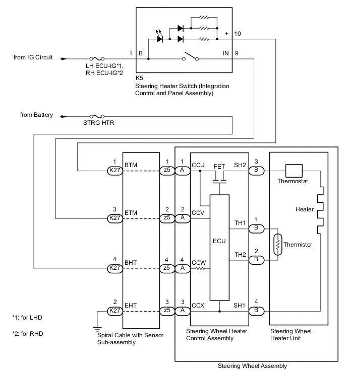
WIRING DIAGRAM
CAUTION / NOTICE / HINT
Tech Tips
-
Inspect the fuses for circuits related to this system before performing the following inspection procedure.
-
The steering wheel heater unit is built into the steering wheel assembly which cannot be disassembled. Therefore, when the steering wheel heater unit has a malfunction, replace the steering wheel assembly.
PROCEDURE
-
INSPECT STEERING WHEEL HEATER UNIT (THERMISTOR/HEATER/THERMOSTAT)
-
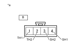
*a Component without harness connected (Steering Wheel Heater Control Assembly) Disconnect the B steering wheel heater control assembly connector.
-
Measure the resistance according to the value(s) in the table below.
Standard Resistance Tester Connection Condition Specified Condition B-1 (TH1) - B-2 (TH2) 10 to 30°C (50 to 86°F) 8.132 to 18.43 kΩ B-4 (SH1) - B-3 (SH2) 20°C (68°F) 1.89 to 2.25 Ω Result Proceed to OK NG
NG 
REPLACE STEERING WHEEL ASSEMBLY Click here
OK 
-
-
INSPECT SPIRAL CABLE WITH SENSOR SUB-ASSEMBLY
-
Check the connectors and cables of the spiral cable with sensor sub-assembly.
OK There are no defects such as scratches, cracks, dents or damage on the connectors or cables. -
Disconnect the K27 and z5 spiral cable with sensor sub-assembly connectors.
-
Measure the resistance according to the value(s) in the table below.
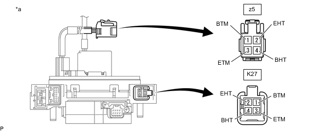
*a Component without harness connected
(Spiral Cable with Sensor Sub-assembly)
- - Standard Resistance Tester Connection Condition Specified Condition z5-1 (BTM) - K27-1 (BTM) Always 3 Ω or less z5-2 (ETM) - K27-3 (ETM) Always 3 Ω or less z5-3 (EHT) - K27-2 (EHT) Always 0.02 to 0.28 Ω z5-4 (BHT) - K27-4 (BHT) Always 0.02 to 0.28 Ω Result Proceed to OK NG
NG
REPLACE SPIRAL CABLE WITH SENSOR SUB-ASSEMBLY Click here
OK
-
-
CHECK STEERING HEATER SWITCH (INTEGRATION CONTROL AND PANEL ASSEMBLY)
-
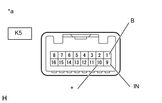
*a Component without harness connected
(Steering Heater Switch (Integration Control and Panel Assembly)
Disconnect the steering heater switch (integration control and panel assembly) connector.
-
Measure the voltage according to the value(s) in the table below.
Tech Tips
As the circuit has a diode, perform the measurement in diode test mode, and do not mistake the polarity.
Standard Voltage Tester Connection (Positive (+) tester probe - Negative (-) tester probe) Switch Condition Specified Condition K5-1 (B) - K5-10 (+) Always Below 1.25 V K5-9 (IN) - K5-10 (+) Steering heater switch is pushed Below 1.25 V -
Measure the resistance according to the value(s) in the table below.
Standard Resistance Tester Connection Switch Condition Specified Condition K5-1 (B) - K5-9 (IN) Steering heater switch is pushed Below 200 Ω K5-1 (B) - K5-9 (IN) Steering heater switch is not pushed 10 kΩ or higher Result Proceed to OK NG
NG
REPLACE STEERING HEATER SWITCH (INTEGRATION CONTROL AND PANEL ASSEMBLY) Click here
OK
-
-
CHECK HARNESS AND CONNECTOR (STEERING HEATER SWITCH (INTEGRATION CONTROL AND PANEL ASSEMBLY) - SPIRAL CABLE WITH SENSOR SUB-ASSEMBLY)
-
Disconnect the K5 steering heater switch (integration control and panel assembly) connector.
-
Disconnect the K27 spiral cable with sensor sub-assembly connector.
-
Measure the resistance according to the value(s) in the table below.
Standard Resistance Tester Connection Condition Specified Condition K5-10 (+) - K27-1 (BTM) Always Below 1 Ω K5-9 (IN) - K27-3 (ETM) Always Below 1 Ω K5-10 (+) or K27-1 (BTM) - Body ground Always 10 kΩ or higher K5-9 (IN) or K27-3 (ETM) - Body ground Always 10 kΩ or higher Result Proceed to OK NG
NG
REPAIR OR REPLACE HARNESS OR CONNECTOR
OK
-
-
CHECK HARNESS AND CONNECTOR (IG CIRCUIT)
-
Disconnect the K5 steering heater switch (integration control and panel assembly) connector.
-
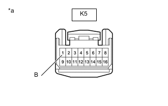
*a Front view of wire harness connector
(to Steering Heater Switch (Integration Control and Panel Assembly))
Measure the voltage according to the value(s) in the table below.
Standard Voltage Tester Connection Switch Condition Specified Condition K5-1 (B) - Body ground Engine switch on (IG) 11 to 14 V Result Proceed to OK NG
NG
REPAIR OR REPLACE HARNESS OR CONNECTOR
OK
-
-
CHECK HARNESS AND CONNECTOR (+B CIRCUIT)
-
Disconnect the K27 spiral cable with sensor sub-assembly connector.
-
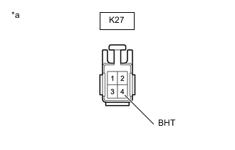
*a Front view of wire harness connector
(to Spiral Cable with Sensor Sub-assembly)
Measure the voltage according to the value(s) in the table below.
Standard Voltage Tester Connection Condition Specified Condition K27-4 (BHT) - Body ground Always 11 to 14 V Result Proceed to OK NG
NG
REPAIR OR REPLACE HARNESS OR CONNECTOR
OK
-
-
CHECK HARNESS AND CONNECTOR (SPIRAL CABLE WITH SENSOR SUB-ASSEMBLY BODY GROUND)
-
Disconnect the K27 spiral cable with sensor sub-assembly connector.
-
Measure the resistance according to the value(s) in the table below.
Standard Resistance Tester Connection Condition Specified Condition K27-2 (EHT) - Body ground Always Below 1 Ω Result Proceed to OK NG
OK
REPLACE STEERING WHEEL HEATER CONTROL ASSEMBLY Click here
NG
REPAIR OR REPLACE HARNESS OR CONNECTOR
-