ELECTRIC PARKING BRAKE SYSTEM Electric Parking Brake System AUTO Function Circuit
DESCRIPTION
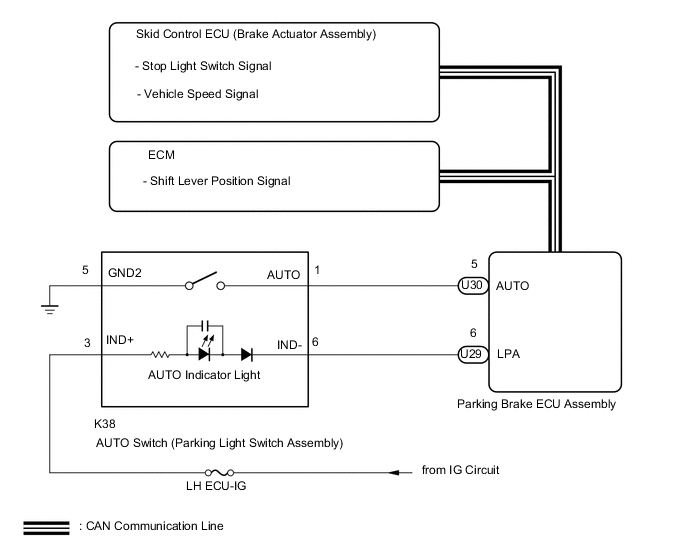
The parking brake ECU assembly receives shift position information from the ECM via CAN communication. Also, the parking brake ECU assembly receives wheel speed information and stop light switch information from the skid control ECU (brake actuator assembly).
The electric parking brake system AUTO control (shift-linked) function automatically releases the parking brake when the following conditions are met: 1) Engine switch on (IG), 2) brake pedal depressed, and 3) shift lever moved out of P. Also, when the shift lever is moved to P with the vehicle in this condition, the function automatically locks the parking brake.
WIRING DIAGRAM
CAUTION / NOTICE / HINT
Note
-
Before disconnecting connectors or fuses, turn the engine switch off and wait 20 seconds or more.
-
If the parking brake ECU assembly is replaced, perform the "Reset Memory" and "Acquire Tension Sensor Zero Point" procedures.
PROCEDURE
-
READ VALUE USING GTS (AUTO SWITCH)
-
Turn the engine switch off.
-
Connect the GTS to the DLC3.
-
Turn the engine switch on (IG) and the GTS on.
-
Enter the following menus: Chassis / Electric Parking Brake / Data List.
-
Check the values by referring to the table below.
Chassis > Electric Parking Brake > Data ListTester Display Measurement Item Range Normal Condition Diagnostic Note Auto Switch AUTO switch (Parking Light Switch Assembly) input information display ON or OFF ON: AUTO switch (Parking Light Switch Assembly) is pressed and held
OFF: AUTO switch (Parking Light Switch Assembly) OFF (released)
When not normal, AUTO switch (Parking Light Switch Assembly) system may be malfunctioning.
Chassis > Electric Parking Brake > Data ListTester Display Auto Switch OK On the GTS screen, item changes between ON and OFF according to switch operation. Result Result Proceed to GTS screen does not display ON even though AUTO switch (parking light switch assembly) is pressed. A GTS screen displays ON while pressing AUTO switch (parking light switch assembly). B
B 
GO TO STEP 4 Click here
A 
-
-
INSPECT AUTO SWITCH (PARKING LIGHT SWITCH ASSEMBLY)
-
Remove the AUTO switch (parking light switch assembly).
-
Inspect the AUTO switch (parking light switch assembly).
Result Proceed to OK NG
NG 
REPLACE PARKING LIGHT SWITCH ASSEMBLY Click here
OK
-
-
CHECK HARNESS AND CONNECTOR (PARKING BRAKE ECU ASSEMBLY - AUTO SWITCH (PARKING LIGHT SWITCH ASSEMBLY))
-
Disconnect the U30 parking brake ECU assembly connector.
-
Disconnect the K38 AUTO switch (parking light switch assembly) connector.
-
Measure the resistance according to the value(s) in the table below.
Standard Resistance Tester Connection Condition Specified Condition U30- 5 (AUTO) - K38-1 (AUTO) Always Below 5 Ω U30- 5 (AUTO) - Body ground Always 100 kΩ or higher K38- 5 (GND2) - Body ground Always Below 5 Ω Result Proceed to OK NG
NG
REPAIR OR REPLACE HARNESS OR CONNECTOR
OK
-
-
READ VALUE USING GTS (P/N/R/D POSITION)
-
Turn the engine switch off.
-
Connect the GTS to the DLC3.
-
Turn the engine switch on (IG) and the GTS on.
-
Enter the following menus: Chassis / Electric Parking Brake / Data List.
-
Check the values by referring to the table below.
Chassis > Electric Parking Brake > Data ListTester Display Measurement Item Range Normal Condition Diagnostic Note P Position Shift lever position input information display ON or OFF ON: Shift lever is in P
OFF: Shift lever is not in P
When not normal, shift position signal system may be malfunctioning N Position Shift lever position input information display ON or OFF ON: Shift lever is in N
OFF: Shift lever is not in N
When not normal, shift position signal system may be malfunctioning R Position Shift lever position input information display ON or OFF ON: Shift lever is in R
OFF: Shift lever is not in R
When not normal, shift position signal system may be malfunctioning D Position Shift lever position input information display ON or OFF ON: Shift lever is in D or M
OFF: Shift lever is not in D or M
When not normal, shift position signal system may be malfunctioning
Chassis > Electric Parking Brake > Data ListTester Display P Position N Position R Position D Position OK On the GTS screen, item changes between ON and OFF according to shift lever operation. Result Result Proceed to OK A NG (for 2UR-GSE with Canister Pump Module) B NG (for 2UR-GSE without Canister Pump Module) C
B
GO TO SFI SYSTEM (HOW TO PROCEED WITH TROUBLESHOOTING) Click here
C
GO TO SFI SYSTEM (HOW TO PROCEED WITH TROUBLESHOOTING) Click here
A
-
-
READ VALUE USING GTS (STOP LIGHT SWITCH)
-
Turn the engine switch off.
-
Connect the GTS to the DLC3.
-
Turn the engine switch on (IG) and the GTS on.
-
Enter the following menus: Chassis / Electric Parking Brake / Data List.
-
Check the values by referring to the table below.
Chassis > Electric Parking Brake > Data ListTester Display Measurement Item Range Normal Condition Diagnostic Note Stop Light Switch Stop light switch assembly input information display ON or OFF ON: Stop light switch ON (brake pedal depressed)
OFF: Stop light switch OFF (brake pedal released)
When not normal, stop light switch system may be malfunctioning
Chassis > Electric Parking Brake > Data ListTester Display Stop Light Switch OK On the GTS screen, item changes between ON and OFF according to switch operation. Result Proceed to OK NG
NG
GO TO VEHICLE STABILITY CONTROL SYSTEM (HOW TO PROCEED WITH TROUBLESHOOTING) Click here
OK
-
-
PERFORM ACTIVE TEST USING GTS (AUTO LIGHT)
-
Turn the engine switch off.
-
Connect the GTS to the DLC3.
-
Turn the engine switch on (IG) and the GTS on.
-
Enter the following menus: Chassis / Electric Parking Brake / Active Test.
-
Check the values by referring to the table below.
Chassis > Electric Parking Brake > Active TestTester Display Measurement Item Control Range Diagnostic Note Auto Light AUTO indicator light ON or OFF
-
Vehicle stopped
-
Engine switch on (IG)
Chassis > Electric Parking Brake > Active TestTester Display Auto Light OK Indicator light turns on when operating the GTS. Result Proceed to OK NG -
OK
REPLACE PARKING BRAKE ECU ASSEMBLY Click here
NG
-
-
CHECK HARNESS AND CONNECTOR (BATTERY - AUTO SWITCH (PARKING LIGHT SWITCH ASSEMBLY))
-
Disconnect the AUTO switch (parking light switch assembly) connector.
-
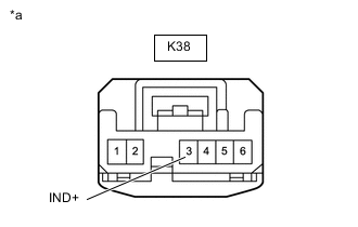
*a Front view of wire harness connector
(to AUTO switch [parking light switch assembly])
Measure the voltage according to the value(s) in the table below.
Standard Voltage Tester Connection Switch Condition Specified Condition K38-3 (IND+) - Body ground Engine switch on (IG) 11 to 14 V Result Proceed to OK NG
NG
REPAIR OR REPLACE HARNESS OR CONNECTOR
OK
-
-
CHECK HARNESS AND CONNECTOR (AUTO SWITCH (PARKING LIGHT SWITCH ASSEMBLY) - PARKING BRAKE ECU ASSEMBLY)
-
Disconnect the K38 AUTO switch (parking light switch assembly) connector.
-
Disconnect the U29 parking brake ECU assembly connector.
-
Measure the resistance according to the value(s) in the table below.
Standard Resistance Tester Connection Condition Specified Condition U29-6 (LPA) - K38-6 (IND-) Always Below 5 Ω U29-6 (LPA) - Body ground Always 100 kΩ or higher Result Proceed to OK NG
OK
REPLACE PARKING BRAKE ECU ASSEMBLY Click here
NG
REPAIR OR REPLACE HARNESS OR CONNECTOR
-