ELECTRIC PARKING BRAKE SYSTEM, Diagnostic DTC:C13AD/23
| DTC Code | DTC Name |
|---|---|
| C13AD/23 | Open in +B Circuit |
DESCRIPTION
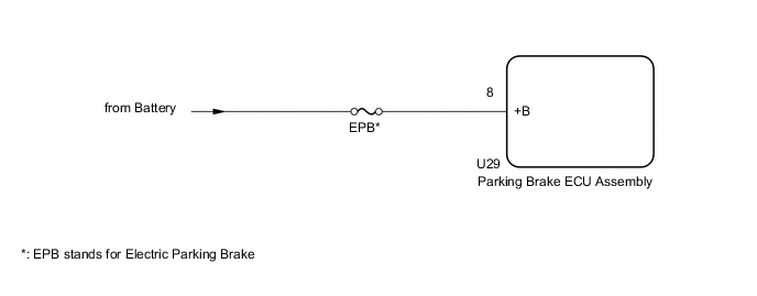
The parking brake ECU assembly is supplied with power to operate the motor via the +B terminals.
| DTC No. | Detection Item | DTC Detection Condition | Trouble Area |
|---|---|---|---|
| C13AD/23 | Open in +B Circuit | All of following conditions are met:
Tech Tips *: This value is based on the assumption that the battery voltage is 12 V. |
|
| Vehicle Condition | |||||
|---|---|---|---|---|---|
| Pattern 1 | Pattern 2 | Pattern 3 | Pattern 4 | ||
| Diagnosis Condition | Engine switch on (IG) | ○ | - | ○ | - |
| Electric parking brake switch assembly pushed to release side with engine switch off | - | ○ | - | ○ | |
| Malfunction Status | When parking brake is not operating: +B voltage is less than 8.5 V* | ○ | ○ | - | - |
| When parking brake is operating: +B voltage is less than 3.5 V* | - | - | ○ | ○ | |
| Detection Time | Approximately 1 second | Approximately 1 second | Approximately 0.5 seconds | Approximately 0.5 seconds | |
| Number of Trips | 1 trip | 1 trip | 1 trip | 1 trip | |
Tech Tips
DTC will be output when conditions for either of the patterns in the table above are met.
-
*: This value is based on the assumption that the battery voltage is 12 V.
WIRING DIAGRAM
CAUTION / NOTICE / HINT
Note
-
Inspect the fuses for circuits related to this system before performing the following inspection procedure.
-
Before disconnecting connectors or fuses, turn the engine switch off and wait 20 seconds or more.
-
If the parking brake ECU assembly is replaced, perform the "Reset Memory" and "Acquire Tension Sensor Zero Point" procedures.
PROCEDURE
-
READ VALUE USING GTS (+B VOLTAGE VALUE)
-
Turn the engine switch off.
-
Connect the GTS to the DLC3.
-
Turn the engine switch on (IG) and the GTS on.
-
Enter the following menus: Chassis / Electric Parking Brake / Data List.
-
Check the values by referring to the table below.
Chassis > Electric Parking Brake > Data ListTester Display Measurement Item Range Normal Condition Diagnostic Note +B Voltage Value Electric parking brake motor power source information display Lo, Mid or Hi Hi -
Chassis > Electric Parking Brake > Data ListTester Display +B Voltage Value OK Values are as shown in normal condition. Result Proceed to OK NG
OK 
USE SIMULATION METHOD TO CHECK Click here
NG 
-
-
CHECK HARNESS AND CONNECTOR (PARKING BRAKE ECU ASSEMBLY - BATTERY)
-
Turn the engine switch off.
-
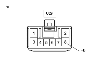
*a Front view of wire harness connector
(to Parking Brake ECU Assembly)
Disconnect the parking brake ECU assembly connector.
-
Measure the voltage according to the value(s) in the table below.
Standard Voltage Tester Connection Condition Specified Condition U29-8 (+B)- Body ground Always 11 to 14 V Result Proceed to OK NG
OK
REPLACE PARKING BRAKE ECU ASSEMBLY Click here
NG
REPAIR OR REPLACE HARNESS OR CONNECTOR
-