BRAKE MASTER CYLINDER(for LHD) INSTALLATION
PROCEDURE
-
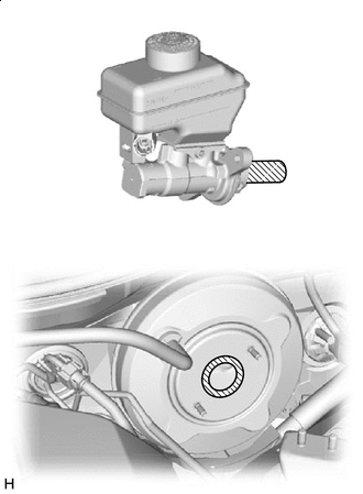
INSTALL BRAKE MASTER CYLINDER O-RING
-
Install a new brake master cylinder O-ring to the brake master cylinder sub-assembly.
-
-
INSTALL BRAKE MASTER CYLINDER SUB-ASSEMBLY
Note
When installing a new brake master cylinder sub-assembly, remove the protectors from the master cylinder piston and outlet ports.
-

Apply Grease Apply a light layer of a grease enclosed with a new brake master cylinder sub-assembly or lithium soap base glycol grease to the circumference of the brake master cylinder sub-assembly and inner surface of the brake booster assembly as shown in the illustration.
-
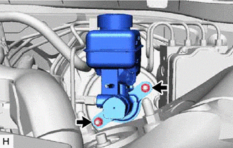
Install the brake master cylinder sub-assembly to the brake booster assembly with the 2 nuts.
- Torque:
- 12.7 N*m { 130 kgf*cm, 9 ft.*lbf }
Note
-
The brake master cylinder sub-assembly requires careful handling. Do not subject the brake master cylinder sub-assembly to any impact, such as from being dropped. Do not reuse a brake master cylinder sub-assembly that has been dropped.
-
Do not hold the brake master cylinder sub-assembly by the master cylinder piston. Hold the brake master cylinder sub-assembly by its body or its reservoir when carrying it.
-
Do not pull out the master cylinder piston.
-
Do not strike or pinch the master cylinder piston, or cause any damage to the master cylinder piston by any other means.
-
When installing the brake master cylinder sub-assembly to the brake booster assembly, or when removing the brake master cylinder sub-assembly from the brake booster assembly, make sure that the brake master cylinder sub-assembly is kept horizontal or with its tip facing downward (the master cylinder piston is facing upward) to prevent the master cylinder piston from falling out.
-
Do not allow any foreign matter to contaminate the master cylinder piston. If any foreign matter gets on the master cylinder piston, remove it by using a piece of new and dry cloth. Do not use water or detergent. Then apply an even layer of lithium soap base glycol grease around the circumference (sliding part) of the master cylinder piston.
-
Do not use any other types of grease.
-
Do not kink or damage the brake lines.
-
Do not allow the brake lines to twist or interfere with other parts or the vehicle body during tightening.
-
Do not allow any foreign matter such as dirt or dust to enter the brake lines from the connecting parts.
-
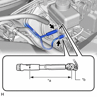
*a Torque Wrench Fulcrum Length *b Union Nut Wrench Using a union nut wrench, connect the 2 brake lines to the brake master cylinder sub-assembly.
- Torque:
- Specified tightening torque
- 19.5 N*m { 199 kgf*cm, 14 ft.*lbf }
Note
-
Do not kink or damage the brake lines.
-
Do not allow the brake lines to twist or interfere with other parts or the vehicle body during tightening.
-
Do not allow any foreign matter such as dirt or dust to enter the brake lines from the connecting parts.
Tech Tips
-
Calculate the torque wrench reading when changing the fulcrum length of the torque wrench.
-
When using a union nut wrench (fulcrum length of 20 mm (0.787 in.)) + torque wrench (fulcrum length of 162 mm (6.378 in.)):
17.4 N*m (177 kgf*cm, 13 ft.*lbf)
-
Connect the connector to the brake master cylinder sub-assembly.
-
Engage the clamp to install the wire harness.
-
-
INSTALL ENGINE ROOM SIDE COVER LH
-
INSTALL WIRING HARNESS CLAMP BRACKET
-
Install the wiring harness clamp bracket with the bolt and nut.
- Torque:
- 8.0 N*m { 82 kgf*cm, 71 in.*lbf }
-
-
INSTALL NO. 3 ENGINE ROOM RELAY BLOCK ASSEMBLY
-
Engage the claw and clamp to install the No. 3 engine room relay block assembly to the wiring harness clamp bracket.
-
-
BLEED BRAKE SYSTEM
-
INSTALL FRONT WHEEL LH